
Emissivity enhanced mid IR source

a technology of ir source and ir ir, which is applied in the field of light sources, can solve the problems of localized cooling, spectral instability, and major problems of source stabilization, and achieve the effects of enhancing the emissivity of ir source, eliminating spectral deficiencies, and enhancing the emission of co-added insulators

Active Publication Date: 2015-03-10
THERMO ELECTRONICS SCI INSTR LLC
View PDF21 Cites 13 Cited by
  • Summary
  • Abstract
  • Description
  • Claims
  • Application Information

AI Technical Summary

Benefits of technology

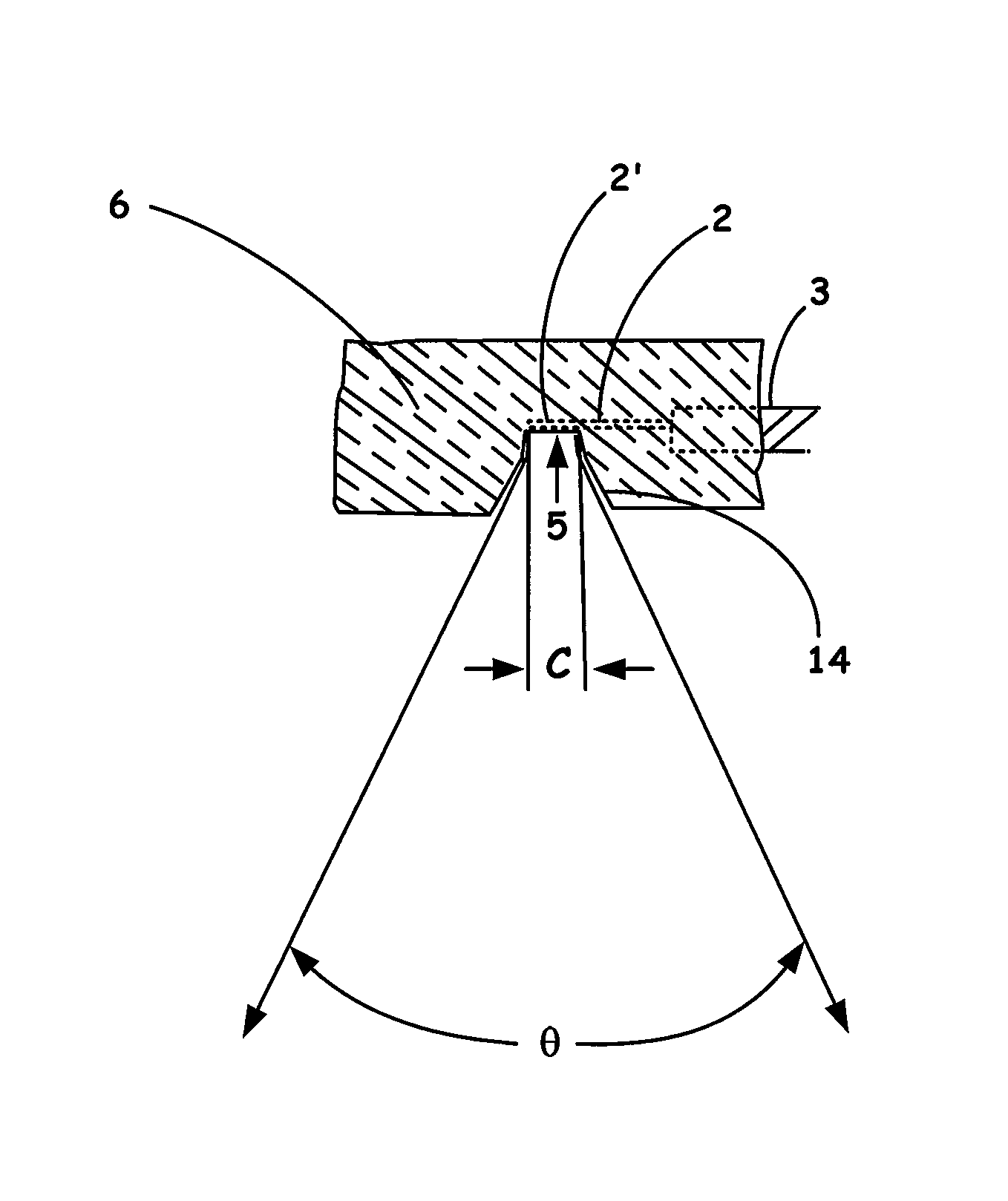
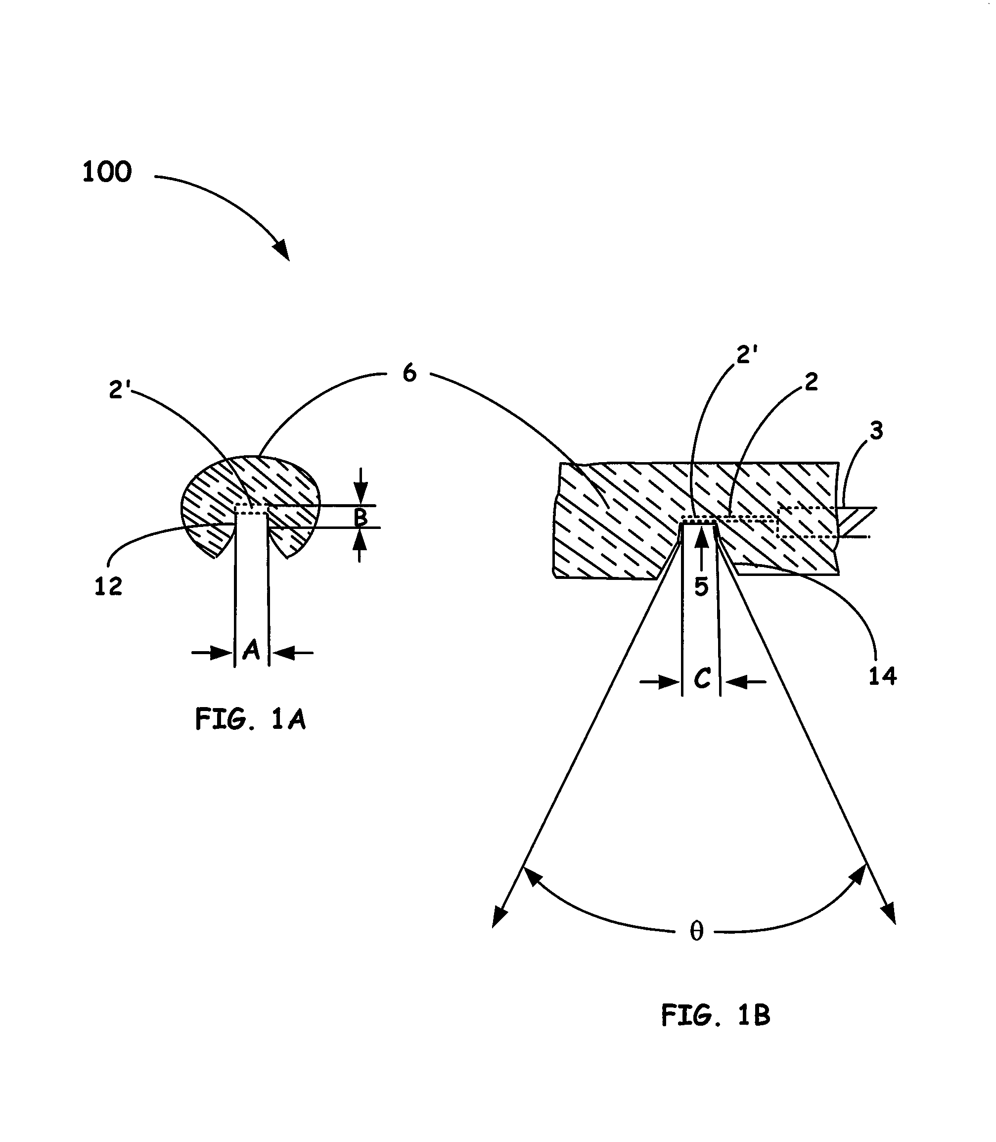
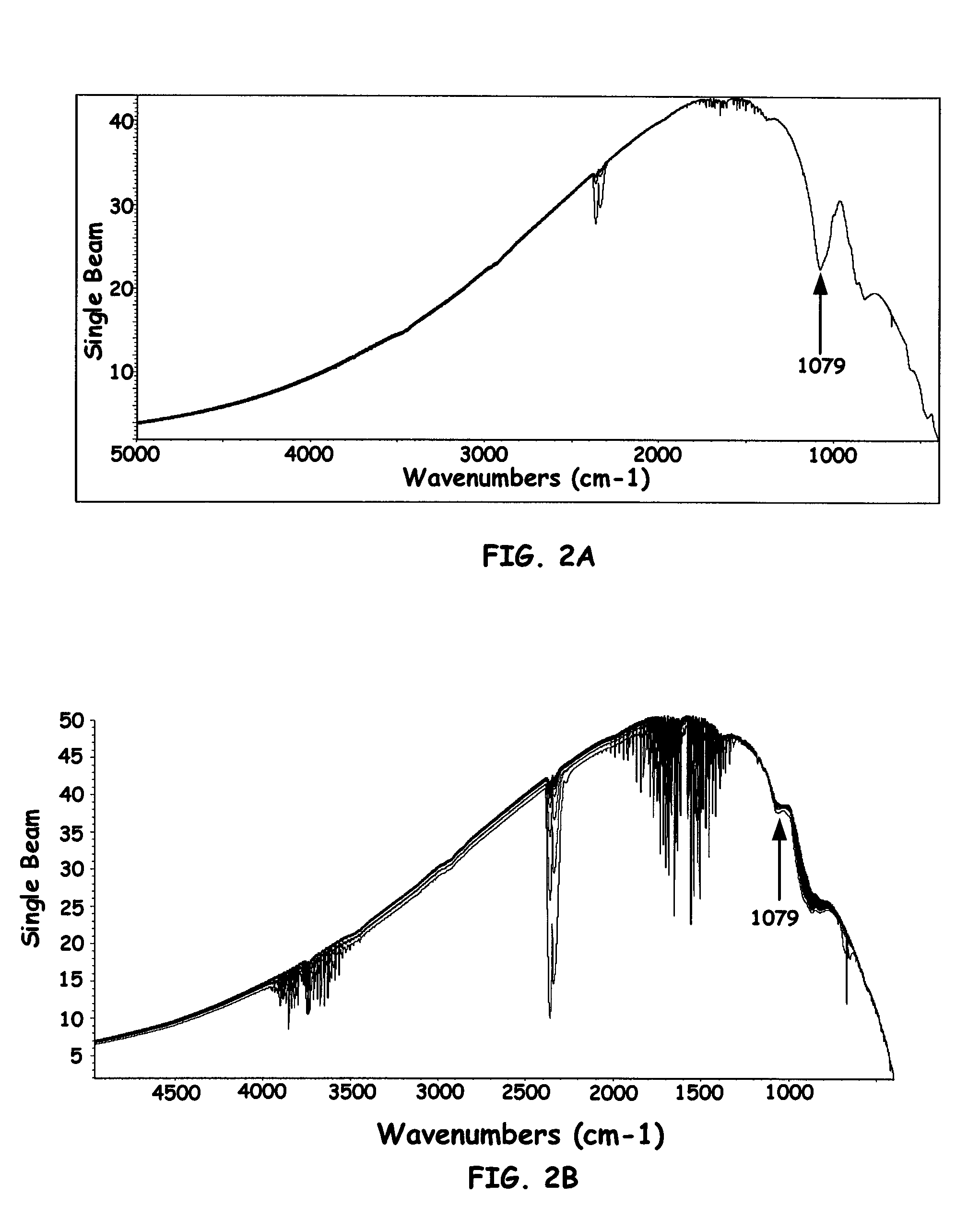
[0008]The present invention thus provides for an infrared source and method that increases (e.g., by up to about 50%) the emissivity in desired optical ranges of the configured source below about 1500 wavenumbers. In particular, the present invention is directed to an infrared source, more often a mid-infrared source that includes a silicon based infrared source element (e.g., silicon nitride, silicon carbide, etc.) in combination with an insulating material, such as, but not limited to aluminum oxide or zirconium oxide, that are configured so that the combination of elements provides for a co-added source spectrum of infrared output illumination. Even more specifically, the insulation itself is machined or modified in a way so that the infrared source element is in contact (e.g., intimate contact) or in close proximity to (i.e., adjacent) with a resultant configured cavity in the insulation so that the IR source image becomes the average of the insulation material and the infrared source element due to the co-added spectra. Such an arrangement of the present invention increases the emissivity of the IR source below about 1500 wave numbers, more often, below about 1100 wave numbers, and even more particularly, at about 1079 wave numbers.
[0009]Accordingly, the present invention provides for an infrared source that includes: an infrared element which provides infrared radiation at desired wavelengths when heated within a predetermined temperature range; an insulator coupled with the infrared element so as to reach a collaborative temperature range provided by the generated heat from the infrared element, wherein the insulator at the collaborative temperature range provides for one or more desired infrared emission spectral bands that co-add with the output emission of the infrared element so as to eliminate spectral deficiencies resulting from the infrared element reaching the collaborative temperature range; and wherein one or more walls of the insulator are configured as a conical interior that converges to an opening that defines an optical aperture of the source so as to enhance emission of the co-added insulator and infrared element and additionally match a field of view of a coupled spectrometer imaging element.

Problems solved by technology

Stabilization of the source, such as when using silicon carbide, however, can be a major issue, especially when the heating element is exposed to ambient conditions.
For example, air turbulence in proximity to the source can cause localized cooling in addition to source noise induced from index of refraction of changes resulting from hot air close to the source and nearby cooler air.
Another egregious instability, however, when using carbide elements as the igniter source, is that as the element is heated to temperatures approaching 1300° C., material changes, such as oxidation and thermal degradation, can produce inhomogeneities in the desired spectral output so as to affect the measurement results and thus necessitating, for example, artificial spectral corrections of the source.
Another source of spectral instability occurs in the imaging of the source itself due to its geometry.
The issue arises in imaging the central portion of the U-shape because there is a resultant loss of emissivity in the central portion as opposed to the outer portions of the optically relayed image directed throughout the spectrometer, which can cause problems when interpreting the spectral information.
Where the infrared element is sealed off from the ambient atmosphere in this manner, potentially corrosive gases will be inhibited from reaching the hot infrared element.
In general, conventional systems that utilize sources described, as discussed above, have had problems associated with imaging of the source as well as material changes in the infrared elements that cause changes in the emitted spectral output.

Method used


Image

  • Emissivity enhanced mid IR source
  • Emissivity enhanced mid IR source
  • Emissivity enhanced mid IR source

Examples


Embodiment Construction

[0017]In the description of the invention herein, it is understood that a word appearing in the singular encompasses its plural counterpart, and a word appearing in the plural encompasses its singular counterpart, unless implicitly or explicitly understood or stated otherwise. Furthermore, it is understood that for any given component or embodiment described herein, any of the possible candidates or alternatives listed for that component may generally be used individually or in combination with one another, unless implicitly or explicitly understood or stated otherwise. Additionally, it is understood that any list of such candidates or alternatives is merely illustrative, not limiting, unless implicitly or explicitly understood or stated otherwise.

[0018]Moreover, unless otherwise indicated, numbers expressing quantities of ingredients, constituents, reaction conditions and so forth used in the specification and claims are to be understood as being modified by the term “about.” Accor...


PUM


Abstract

An infrared (IR) source apparatus that includes a desired infrared source element coupled to an insulating housing so to minimize overall source inefficiency at desired optical bandwidths is introduced. The insulation itself is machined or configured in a way so that the infrared source element is in contact with a designed cavity in the insulation so that the IR source image becomes the average of the insulation material and the infrared element. Such an arrangement of the present invention increases the emissivity of the IR source below about 1500 wave numbers, more often, below about 1100 wave numbers, and even more particularly, at about 1079 wave numbers. Accordingly, the combined emissivity of the infrared source and the insulation substantially enhances spectral emission and eliminates or reduces spectral artifacts from the formation of oxides on the infrared source surfaces.

Description

FIELD OF THE INVENTION[0001]The present invention relates to the field of light sources and more particularly, to infrared sources utilized in analytical instruments, such as infrared spectrometers.BACKGROUND OF THE INVENTION[0002]Conventional infrared emission sources typically utilize a wire, metal or ceramic element that is heated to emit a continuous band of optical radiation. In particular, the source elements, e.g., an infrared igniter source element, that is incorporated into infrared spectrometers, such as, FTIR instruments, are often modifications or adaptations of commercial heating elements. Examples include filaments configured from resistive electrical conductive materials, such as Kanthal, (i.e., alloys known for their ability to withstand high temperatures and having intermediate electric resistance) and those manufactured from silicon carbide. Another example includes the use of a silicon nitride-tipped glo-plug used for preheating the combustion chamber in a diesel ...

Claims


Application Information

Patent Timeline
Patent Type & Authority Patents(United States)
IPC IPC(8): A61N5/06G01J3/10
CPCG01J3/108
Inventor IVERSON, JOHN R.COFFIN, JOHN MAGIE
Owner THERMO ELECTRONICS SCI INSTR LLC
Learn More