Polarizing sheet removing tool and removing method

a technology of polarizing sheets and tools, applied in the direction of instruments, lamination ancillary operations, optics, etc., can solve the problems of difficult to completely peel off the polarizing sheets, difficult operation, and strong adhesion force, so as to save the time used to remove, the effect of simple structure and convenient operation

Inactive Publication Date: 2015-03-24
TCL CHINA STAR OPTOELECTRONICS TECH CO LTD
View PDF13 Cites 3 Cited by
  • Summary
  • Abstract
  • Description
  • Claims
  • Application Information

AI Technical Summary

Benefits of technology

[0008]An object of the present invention is to provide a polarizing sheet removing tool, which has a simple structure, is easy to operate, can effectively save the time used to remove the polarizing sheet, and is of high efficiency.
[0009]Another object of the present invention is to provide a polarizing sheet removing method, which effectively shorten removing time of polarizing sheet, increase efficiency of peeling off polarizing sheet, and improve the result of peeling.
[0031]The efficacy of the present invention is that the present invention provides a polarizing sheet removing tool and removing method, which uses a tool on which a piston device and adhesive dissolving liquid are provided so that in an operation of removing a polarizing sheet, the adhesive dissolving liquid contained in the handle is guided by a guide tube toward a blade for subsequently flowing toward the bonding adhesive to dissolve the bonding adhesive, thereby making the polarizing sheet easily removable, shortening removing time of the polarizing sheet, and improving removing efficiency and removing performance.

Problems solved by technology

However, it is inevitable that the adhesion force interferes with the removal of the adhesion force to some extents.
However, it is often that the adhesion force is relatively strong and it is hard to completely peel off the polarizing sheet.
This portion of adhesive is difficult to remove and removal is usually done by applying the cutter multiple times. This severely affects the speed and result of peeling of polarizing sheet and lowers down the efficiency of experimental analyses.

Method used


Image

  • Polarizing sheet removing tool and removing method
  • Polarizing sheet removing tool and removing method
  • Polarizing sheet removing tool and removing method

Examples


Embodiment Construction

[0038]To further expound the technical solution adopted in the present invention and the advantages thereof, a detailed description is given to a preferred embodiment of the present invention and the attached drawings.

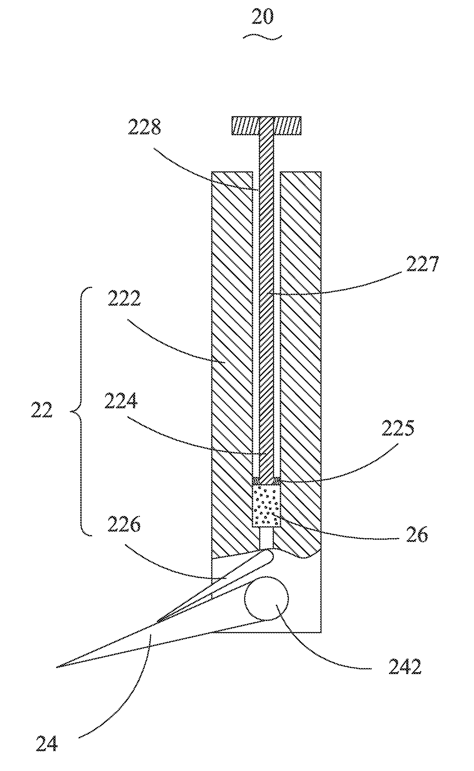
[0039]Referring to FIGS. 2 and 3, the present invention provides a polarizing sheet removing tool 20, which comprises a handle 22 and a blade 24 mounted on the handle 22. The handle 22 comprises a main body 222, a piston device 224 mounted on the main body 222, and a guide tube 226 mounted on the main body 222. The main body 222 forms therein a channel 228 for containing an adhesive dissolving liquid 26. The piston device 224 is mounted inside the channel 228. The guide tube 226 has an end in communication with the channel 228 and an opposite end positioned on the blade 24 to guide the adhesive dissolving liquid 26 contained in the channel 228 to the blade 24. The adhesive dissolving liquid 26 flows over the blade 24 to reach bonding adhesive 46 between a substrate 42 ...


PUM

PropertyMeasurementUnit
included angleaaaaaaaaaa
diameteraaaaaaaaaa
electric fieldaaaaaaaaaa

Abstract

The present invention provides a polarizing sheet removing tool and removing method. The tool includes a handle and a blade mounted on the handle. The handle includes a main body, a piston device mounted on the main body, and a guide tube mounted on the main body. The main body forms therein a channel for containing an adhesive dissolving liquid. The piston device is mounted inside the channel. The guide tube has an end in communication with the channel and an opposite end positioned on the blade to guide the adhesive dissolving liquid contained in the channel to the blade. The present invention uses a tool on which a piston device and adhesive dissolving liquid are provided so that in removing a polarizing sheet, the adhesive dissolving liquid can be guided by a guide tube toward a blade for subsequently flowing toward and dissolving bonding adhesive.

Description

BACKGROUND OF THE INVENTION[0001]1. Field of the Invention[0002]The present invention relates to the field of manufacturing liquid crystal display panels, and in particular to a polarizing sheet removing tool and removing method.[0003]2. The Related Arts[0004]Liquid crystal displays (LCDs) have numerous advantages, such as thin device body, less power consumption, and being free of radiation, and is thus widely used. Most of the flat panel display devices available in the market are backlighting liquid crystal displays, which comprise a liquid crystal display panel and a backlight module. The operation principle of the liquid crystal display panel is that liquid crystal molecules are arranged between two parallel glass substrates and electricity is selectively applied to circuits of the glass substrates to control change of the orientation of the liquid crystal molecules in order to refract out the light from a backlight module for formation of an image.[0005]Referring to FIG. 1, a ...

Claims


Application Information

Patent Timeline
Patent Type & Authority Patents(United States)
IPC IPC(8): B32B38/10B26B27/00B26D3/28B26D7/08G02F1/1335
CPCB26D7/08B26B27/00B26D3/28G02F1/133528G02F2202/28Y10S156/934Y10S156/937B32B38/10B32B43/006G02F1/1303G02F1/1309Y10T83/0443Y10T156/1111Y10T156/1126Y10T156/1132Y10T156/1168Y10T156/1184Y10T156/1189Y10T156/1928Y10T156/1933Y10T156/1961Y10T156/1967Y10T156/1972
Inventor ZHUANG, YIZHUANGTSAI, JUNGMAOLIAO, SHIUESHIHWEN, SONGXIANDENG, MINGFENG
Owner TCL CHINA STAR OPTOELECTRONICS TECH CO LTD
Why Eureka
Try Eureka