

Electrical connector
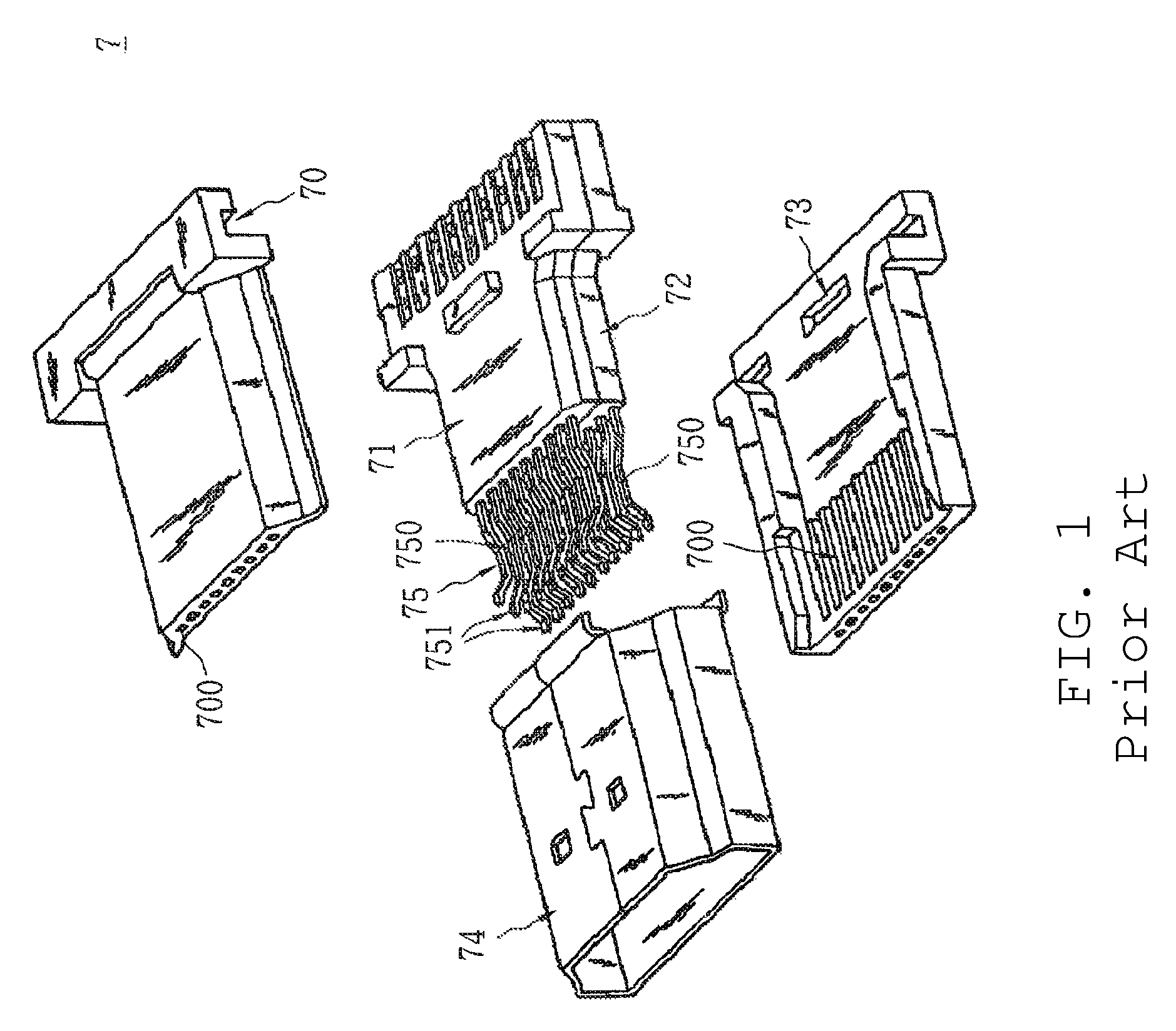
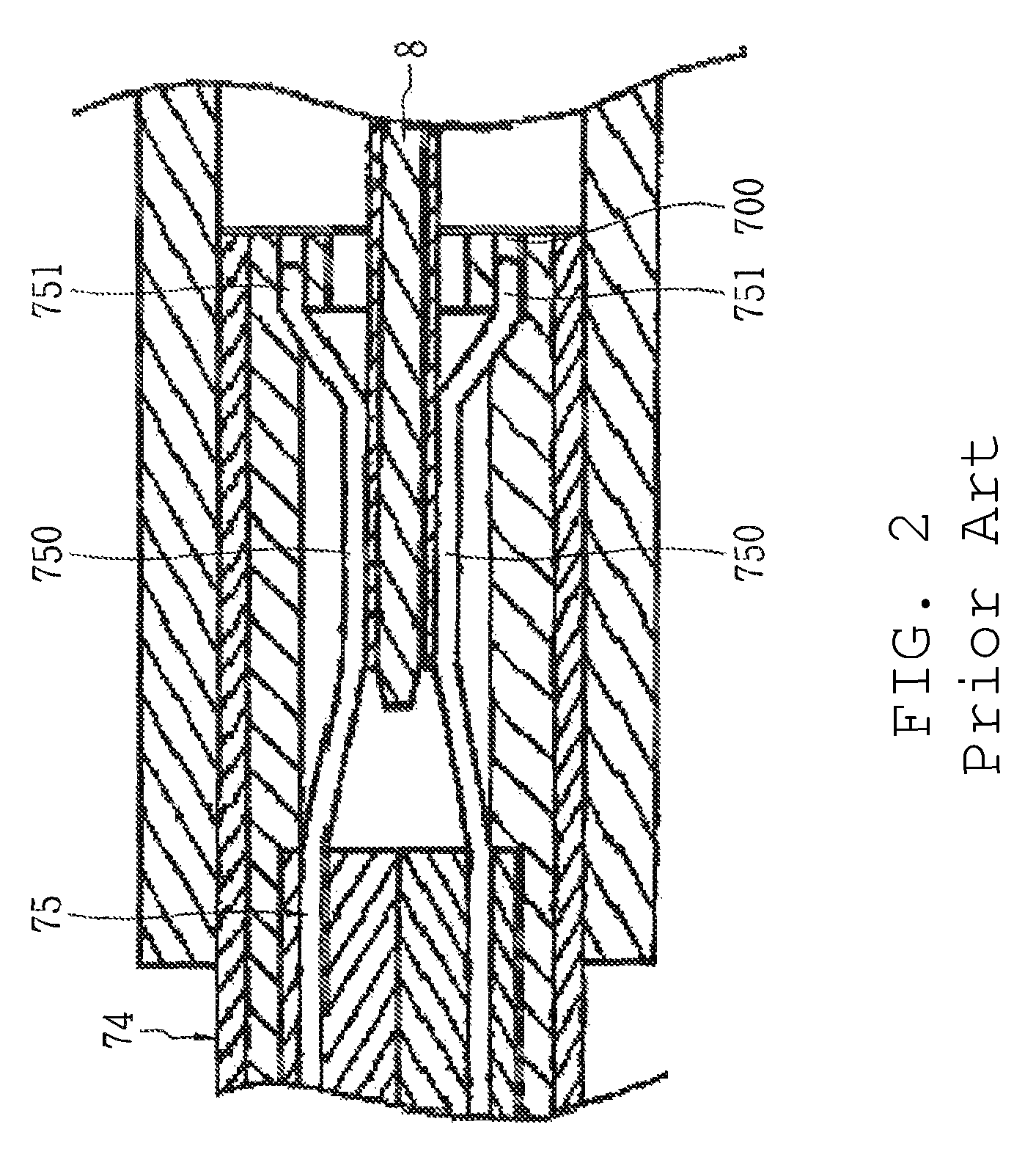
a technology of electrical connectors and connectors, applied in the direction of coupling contact members, coupling device connections, coupling protection earth/shielding arrangements, etc., can solve the problems of affecting the stability of electrical connections and signal transmission quality, the thickness of connectors b>7/b> is quite thick, and the difficulty of tightly mate electrical connectors
- Summary
- Abstract
- Description
- Claims
- Application Information
AI Technical Summary
Benefits of technology
Problems solved by technology
Method used
Image

Examples
Embodiment Construction
[0018]The detailed description that follows describes exemplary embodiments and is not intended to be limited to the expressly disclosed combination(s). Therefore, unless otherwise noted, features disclosed herein may be combined together to form additional combinations that were not otherwise shown for purposes of brevity.
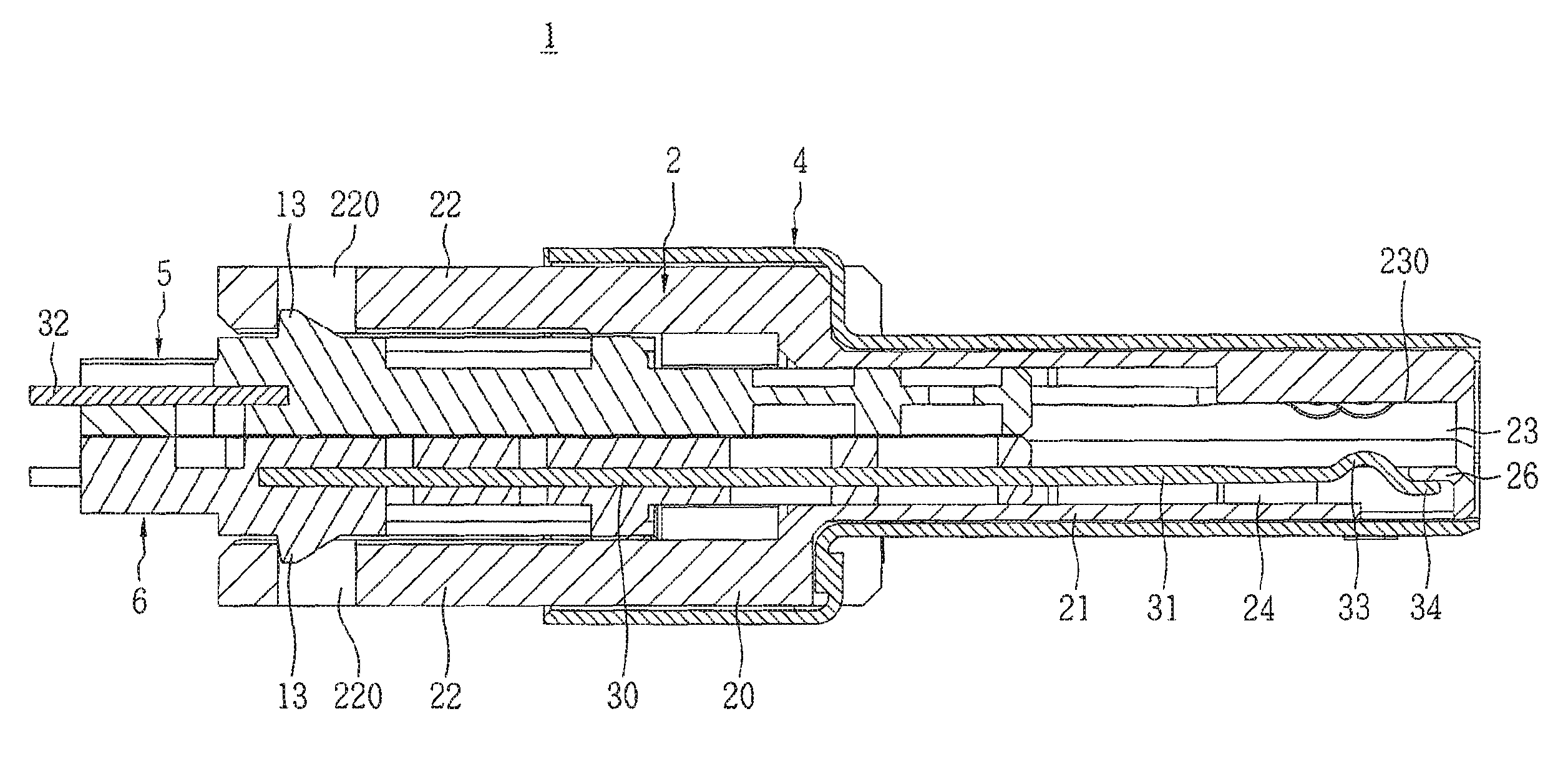
[0019]As can be appreciated by the details described below, in the depicted an embodiment of the depicted electrical connector, the contact portion of the terminals can experience elastic movement within the terminal grooves, and it does not rely solely upon the elastic deformation of its own material as in prior art. Therefore, it is possible to maintain tight contact with another socket connector after a long period of use and thus avoid poor contact between mating terminals. As a result, the electrical connector has relatively higher operating stability and a fairly long life. In addition, by thinning the abutting portion of the terminals, it is possible to inc...
PUM
 Abstract
Description
Claims
Application Information