Device for reducing noise from jet-pylon interactions on jet engines

Active Publication Date: 2015-03-31
SN DETUDE & DE CONSTR DE MOTEURS DAVIATION S N E C M A
View PDF12 Cites 5 Cited by
  • Summary
  • Abstract
  • Description
  • Claims
  • Application Information

AI Technical Summary

Benefits of technology

[0020]In one particular embodiment, the pylon comprises at least one orifice (8) positioned on that part of its flank that is situated outside of the cold flow of the turbojet engine. The injection of fluid through this orifice also seeks to reduce the turbulent intensity of the flows in this region outside the flow from the engine. This results in a cleaner airflow, which therefore generates less noise, and contributes to the mixing with the secondary or bypass flow.
[0021]For preference,

Problems solved by technology

One of the main sources of this noise is from the jet of the engines, which are used at full power during the takeoff phase.
The presence of the pylon, i.e. of the strut that supports the engine by attaching it to the wing, generates locally, in the region where the gases are ejected, high levels of turbulence in the flow and this results in a very significant increase in the lateral noise of the engine.
The results of numerical calculations or of measurements taken on models in a wind tunnel clearly show that the effects of interactions between the flow flowing around the pylon and the pylon itself generate an appreciable increase in the levels of turbulence and, as a

Method used


Image

  • Device for reducing noise from jet-pylon interactions on jet engines
  • Device for reducing noise from jet-pylon interactions on jet engines
  • Device for reducing noise from jet-pylon interactions on jet engines

Examples


Embodiment Construction

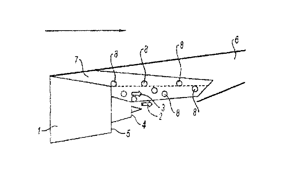
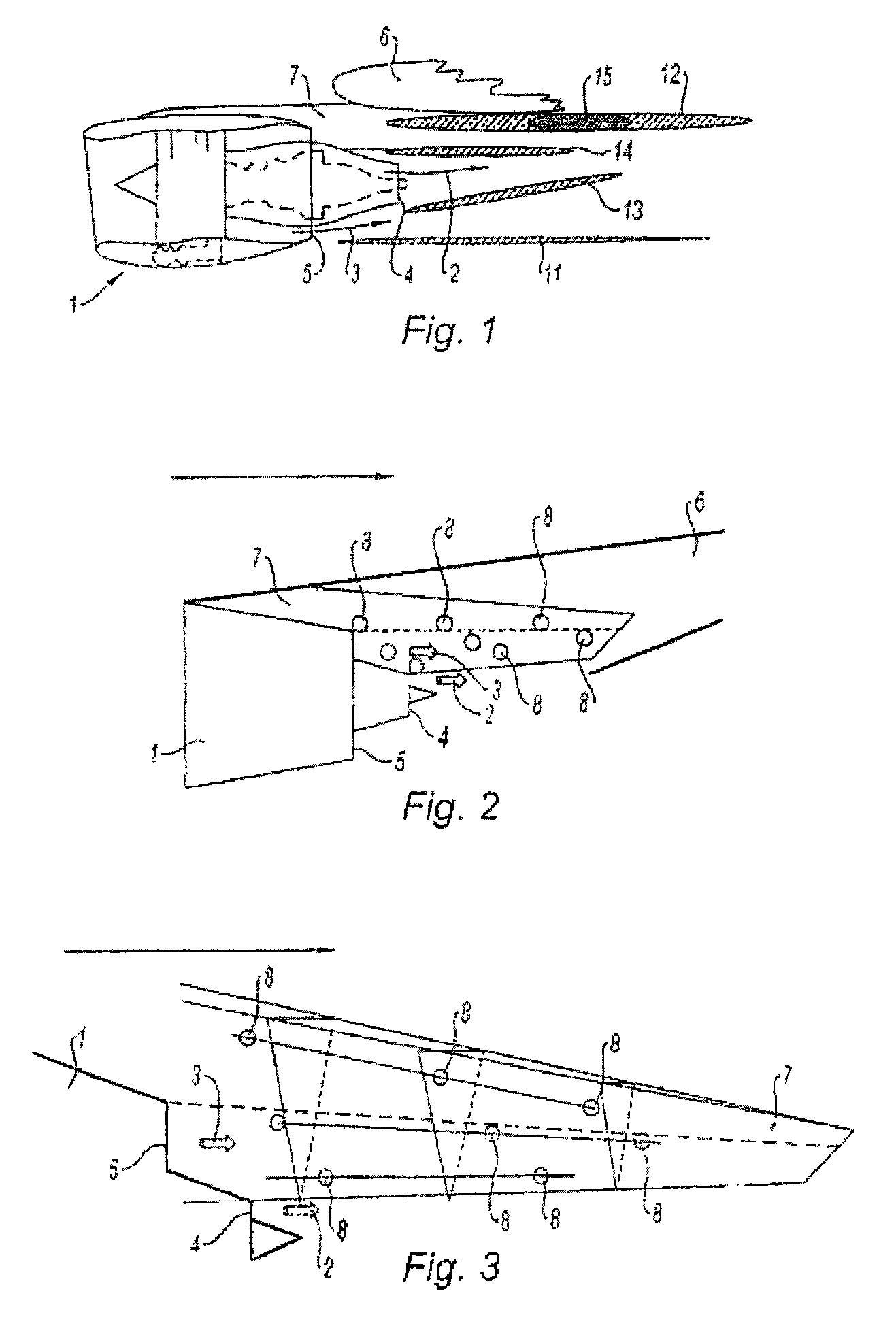
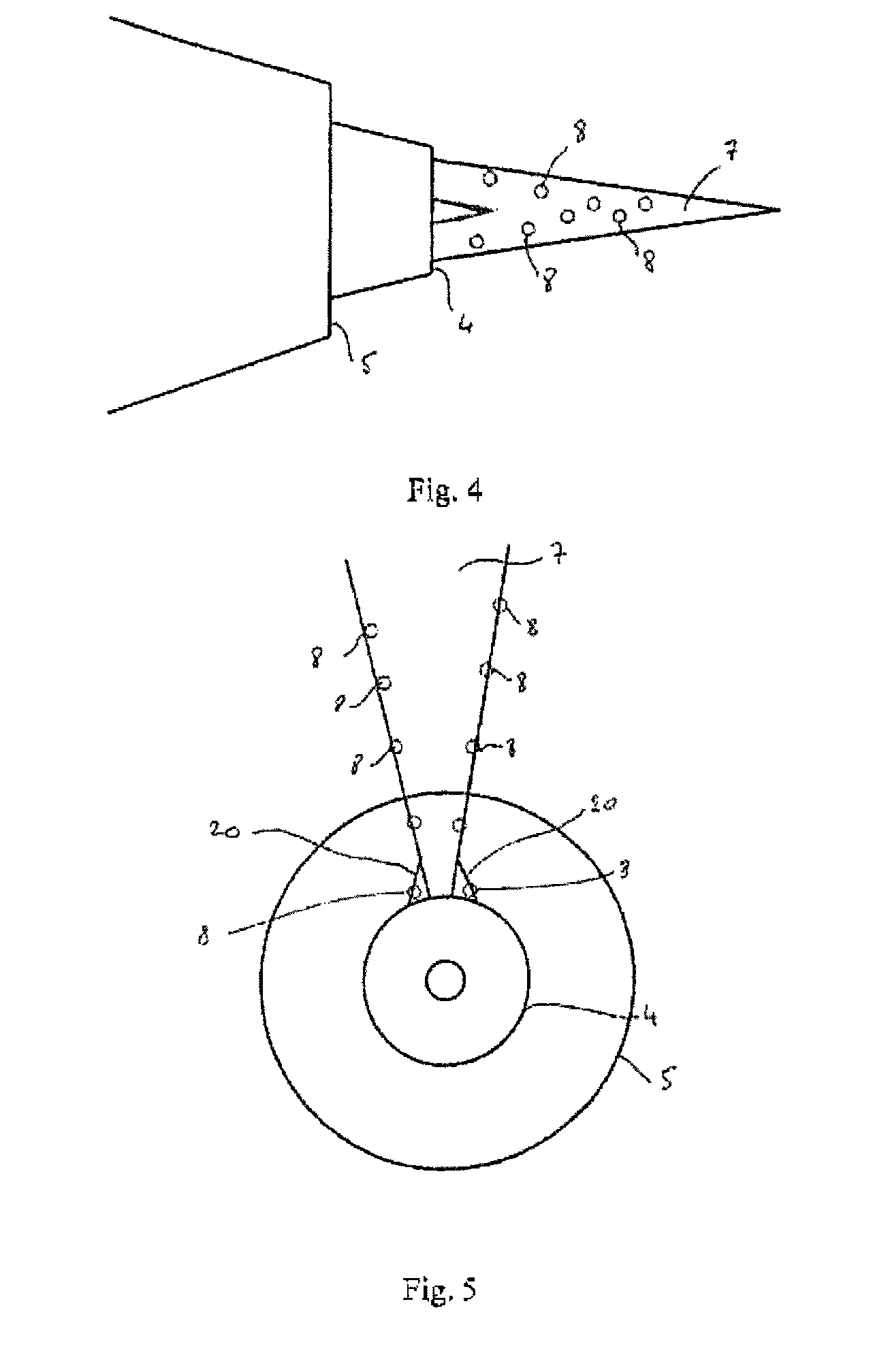
[0033]Reference is made to FIG. 1 which shows an engine 1, of the dual-flow or bypass turbojet engine type, from which there are exhausted a primary flow or hot flow 2, and a secondary or bypass flow, also known as the cold flow 3. The hot flow leaves the engine 1 at a primary exit nozzle 4 whereas the cold flow leaves at a secondary exit nozzle 5. The engine 1 is attached to a wing 6 of an airplane (not depicted) by a supporting pylon 7. The pylon 7 is of substantially planar shape with an upper face for connecting to the airplane, two lateral flanks, here depicted as substantially vertical and mutually parallel, and a lower face or sole. Fairings 20, visible in FIG. 5, make the connection between the flanks of the pylon 7 and the top of the primary exit nozzle 4, so as to ensure a clean aerodynamic flow at the junction between these two elements. The pylon 7 runs longitudinally, i.e. in the direction in which the air flows around the engine, downstream of the exit plane of the exi...


PUM


Abstract

An aircraft pylon for mounting a dual-flow or triple-flow jet engine, the pylon including an upper surface for connection to the aircraft, two side flanks, and a flange on the lower portion of the pylon. The pylon further includes at least one portion that extends downstream from the cold flow nozzle of the jet engine and lies in the cold flow and, on the portion thereof extending into the cold flow beyond the nozzle, at least one opening, positioned on one of the flanks of the pylon, by which an air stream is injected into or drawn from the gas flow that flows along the flanks of the pylon.

Description

BACKGROUND OF THE INVENTION[0001]1. Field of the Invention[0002]The field of the present invention is that of civil aviation and, in particular, that of the noise generated by airplanes.[0003]2. Description of the Related Art[0004]The noise generated by commercial airplanes, particularly on takeoff, is a nuisance that is widely known and a great many innovations have been conceived in an attempt to reduce it. One of the main sources of this noise is from the jet of the engines, which are used at full power during the takeoff phase. Considerable work has obviously been carried out in an attempt to reduce the noise of the jet of the turbojet engine, for example the fitting of sawtooth chevrons to the exit nozzle, whether the exit nozzle for the hot gases which originate from the primary flow through the engine, or the one for the so-called cold gases which originate from the secondary or bypass flow of the engine.[0005]In order to limit the nuisance to those living or working near air...

Claims


Application Information

Patent Timeline
IPC IPC(8): B64B1/24B64C7/02B64C21/02B64D27/18F02K1/34
CPCB64C21/02B64C7/02B64D27/18B64D33/06Y02T50/166Y02T50/10
Inventor DRAVET, ALAINJULLIARD, JACQUES MICHEL ALBERTLOHEAC, PIERRE PHILIPPE MARIE
Owner SN DETUDE & DE CONSTR DE MOTEURS DAVIATION S N E C M A
Why Eureka
Try Eureka