
Implant-catheter attachment mechanism using snare and method of use

a technology of snare and attachment mechanism, which is applied in the field of occlusion devices, can solve the problems of recurrent cerebrovascular events, adverse side effects, and umbrella devices and the like designed for asds that are not optimally suited for use as pfo closure devices, so as to reduce maintain the axial length of the device.

Active Publication Date: 2015-03-31
WL GORE & ASSOC INC
View PDF67 Cites 13 Cited by
  • Summary
  • Abstract
  • Description
  • Claims
  • Application Information

AI Technical Summary

Benefits of technology

The solution enables a more secure and anatomically conformable closure of PFOs, reducing the risk of complications and improving deployment consistency, while allowing for controlled expansion and contraction of the occluder for easy retrieval and repositioning.

Problems solved by technology

While there is currently no definitive proof of a cause-effect relationship, many studies have confirmed a strong association between the presence of a PFO and the risk for paradoxical embolism or stroke.
In addition, there is significant evidence that patients with a PFO who have had a cerebral vascular event are at increased risk for future, recurrent cerebrovascular events.
These patients are commonly treated with oral anticoagulants, which potentially have adverse side effects, such as hemorrhaging, hematoma, and interactions with a variety of other drugs.
However, umbrella devices and the like that are designed for ASDs are not optimally suited for use as PFO closure devices.
Currently available septal closure devices present drawbacks, including technically complex implantation procedures.
Additionally, there are significant complications due to thrombus, fractures of the components, conduction system disturbances, perforations of heart tissue, and residual leaks.
Many devices have high septal profile and include large masses of foreign material, which may lead to unfavorable body adaptation of a device.
Given that ASD devices are designed to occlude holes, many lack anatomic conformability to the flap-like anatomy of PFOs.
Thus, when inserting an ASD device to close a PFO, the narrow opening and the thin flap may form impediments to proper deployment.
Even if an occlusive seal is formed, the device may be deployed in the heart on an angle, leaving some components insecurely seated against the septum and, thereby, risking thrombus formation due to hemodynamic disturbances.
Finally, some septal closure devices are complex to manufacture, which may result in inconsistent product performance.
Such delivery systems are not generally suited for delivering a device that does not readily expand into the deployed configuration.
Further, the delivery systems of the prior art may not allow verification of the position of the device prior to full deployment of the device.
Finally delivery systems of the prior art may not be suitable to manipulate the configuration of the device in a secure manner to allow for complete deployment of the device.

Method used


Image

  • Implant-catheter attachment mechanism using snare and method of use
  • Implant-catheter attachment mechanism using snare and method of use
  • Implant-catheter attachment mechanism using snare and method of use

Examples


embodiment 600

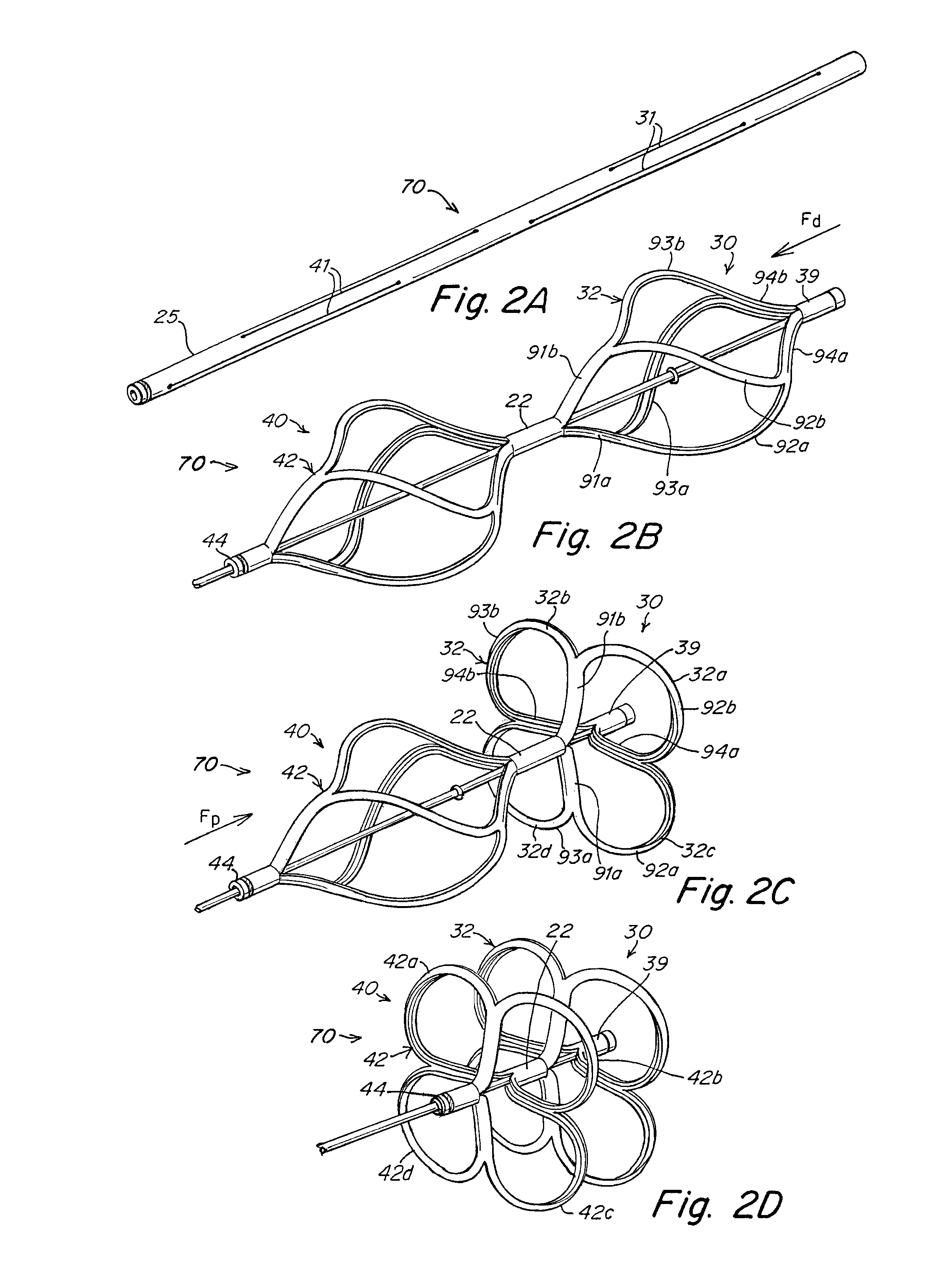
[0133]FIGS. 34A-C illustrate an alternative embodiment 600 of an occluder delivery system using a delivery wire with an alternative second securement system. In this embodiment, the proximal end of the catch element screws onto the proximal end of the occluder to secure it at a deployed configuration. FIG. 34A is an exploded perspective view of a catch member 650 and first securement system 610. Catch member 650 can be disposed in the radially central portion of the occluder 70, and includes a distal flange 652, a proximal end 654, and a catch body 656. The flange 652 rests against the distal end of the occluder 76 as described above, for manipulating the occluder 70 during delivery and / or retrieval and for catching the occluder 70 in the deployed position. The distal end of the catch member 650 is allowed to rotate freely relative to the occluder 70, as described below. The proximal end 654 of the catch member 650 includes external threads 656 that cooperate with internal threads 6...

embodiment 800

[0142]FIGS. 41 and 42 illustrate an alternative embodiment 800 of an occluder delivery system for occluder 820 and catch member 830, employing an alternate second securement system. FIG. 41 shows a close-up view of the distal end of the catheter portion 800 of the delivery system 850. Delivery catheter 802 is a dual-lumen catheter that comprises a first, center lumen 804 and a second side lumen 810. A delivery wire 806 is contained in the center lumen 804. The delivery wire 806 includes an internally threaded portion 832 on its distal end 808. The internally threaded portion 832 cooperates with an externally threaded portion 834 on catch member 830 to form a threaded connection that provides a first securement system, as discussed with reference to FIG. 8, for example. Although the embodiment illustrated in FIGS. 41 and 42 incorporates this threaded first securement system, any first securement system that provides the needed delivery, deployment and / or retrieval features may be use...


PUM


Abstract

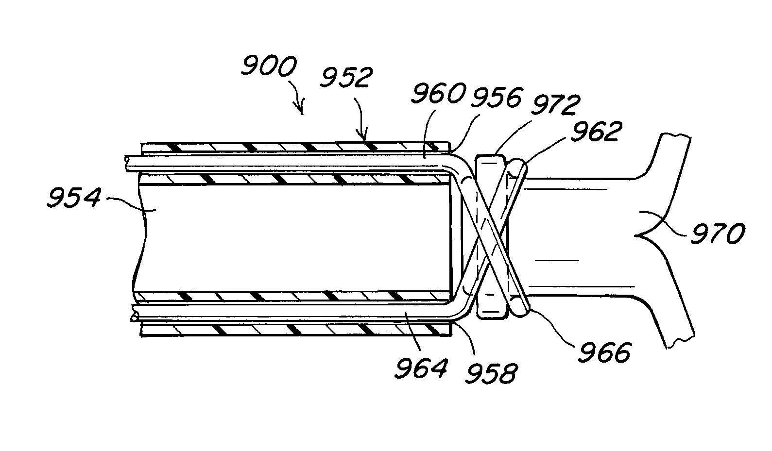
Devices, delivery systems and delivery techniques for an occlusion device for the closure of physical anomalies, such as an atrial septal defect, a patent foramen ovale (PFO), and other septal and vascular defects are described. The devices, delivery systems and delivery techniques relate particularly to, but are not limited to, a patent foramen ovale (PFO) occluder made from a polymer tube. The securement systems enable the deployment (and retrieval) of the device. In one aspect, the second securement system employs a snare connection. The snare connection may have various configurations, including a single snare, double snare, and double criss-cross snare. The securement systems are detached when the device has been properly positioned. The securement systems can be manipulated by control systems provided in the control portion of the delivery system.

Description

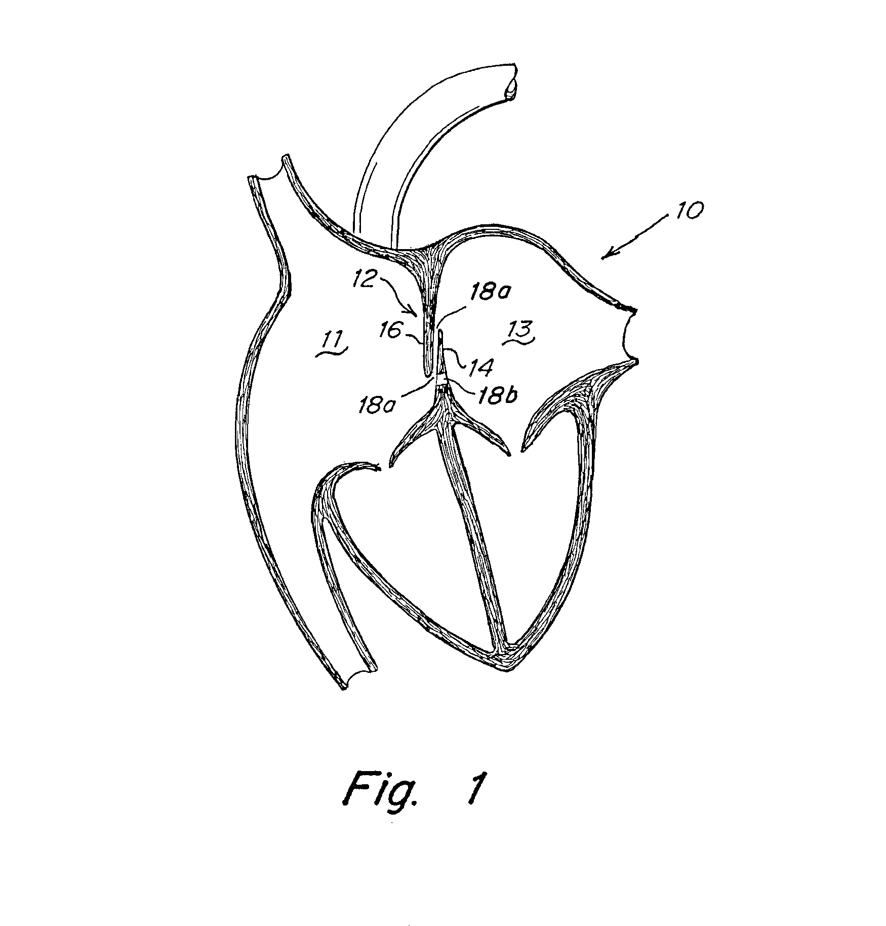
CROSS REFERENCE TO RELATED APPLICATIONS[0001]This application claims the benefit of provisional application U.S. Ser. No. 60 / 847,703 filed Sep. 28, 2006, the contents of which are incorporated by reference.TECHNICAL FIELD[0002]This invention relates generally to occlusion devices for the closure of physical anomalies, such as an atrial septal defect, a patent foramen ovale, and other septal and vascular defects. The invention also relates to delivery systems and mechanisms for such devices.BACKGROUND[0003]A patent foramen ovale (PFO), illustrated in FIG. 1, is a persistent, one-way, usually flap-like opening in the wall between the right atrium 11 and left atrium 13 of the heart 10. Because left atrial (LA) pressure is normally higher than right atrial (RA) pressure, the flap usually stays closed. Under certain conditions, however, right atrial pressure can exceed left atrial pressure, creating the possibility that blood could pass from the right atrium 11 to the left atrium 13 and ...

Claims


Application Information

Patent Timeline
Patent Type & Authority Patents(United States)
IPC IPC(8): A61F11/00A61B17/00
CPCA61B17/0057A61B2017/00575A61B2017/00592A61B2017/00606A61B2017/00619A61B2017/00623A61B2017/00867
Inventor CAHILL, RYAN
Owner WL GORE & ASSOC INC
Learn More