
Self-shield open magnetic resonance imaging superconducting magnet

a superconducting magnet, self-shield technology, applied in the direction of superconducting magnets/coils, magnetic field measurement using superconductive devices, instruments, etc., can solve the problems of difficult to meet the need for openness in interventional therapy, unsatisfactory openness, cabin fever for some patients, etc., to achieve better electromagnetic compatibility and lower the requirement of floor space

Active Publication Date: 2015-03-31
INST OF ELECTRICAL ENG CHINESE ACAD OF SCI
View PDF6 Cites 0 Cited by
  • Summary
  • Abstract
  • Description
  • Claims
  • Application Information

AI Technical Summary

Benefits of technology

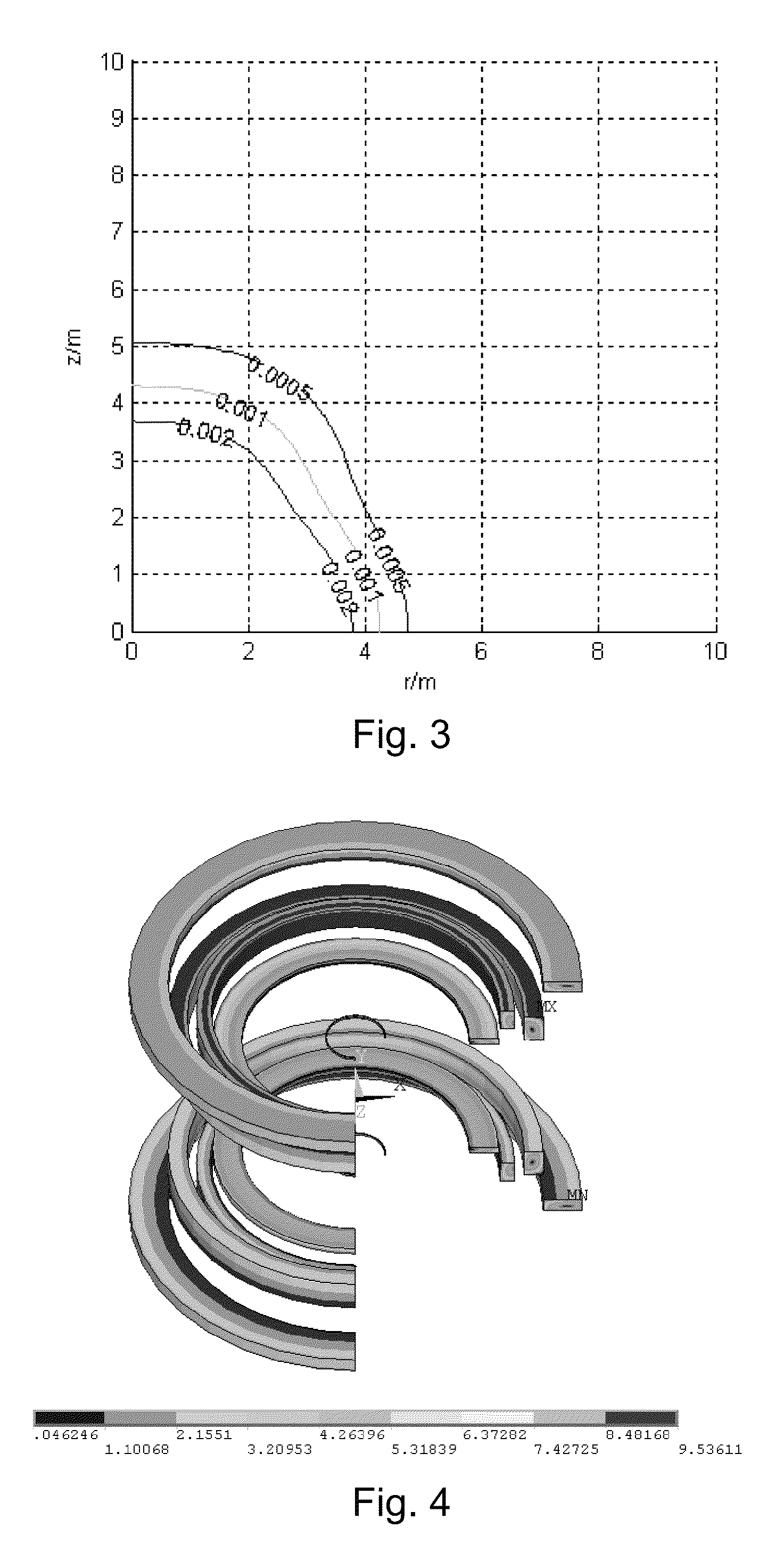
This configuration achieves a non-homogeneity of 5 ppm within a 360 mm DSV, maintains a maximum magnetic field below 9.5 T, and minimizes stray fields, ensuring electromagnetic compatibility and adequate openness for whole-body imaging and interventional therapy, while being compact enough for larger patients and requiring less floor space.

Problems solved by technology

However, magnet structures in form of tunnel have unsatisfied openness, and may cause cabin fever for some patients.
Although many new structural magnet systems have emerged in recent years, such as a short cavity magnet structure with magnet lengths from 1.3 m to 1.4 m, it is still difficult to meet the need for openness in interventional therapy.
At present, there are no 1.5 T fully-open MRI systems available in the world.
The main difficulty in open MRI magnets with superconducting coils lies in high cost and difficulties in fabrication technology.
For open superconducting magnet structures with passive shield, the magnet system will become too big due to the incorporation of ferromagnetic shield.
For example, in the case of a 1.5 T central magnetic field, the maximum magnetic field within the coils may even exceed 10 T, which is not acceptable for superconducting coils adopting NbTi as their material.

Method used


Image

  • Self-shield open magnetic resonance imaging superconducting magnet
  • Self-shield open magnetic resonance imaging superconducting magnet
  • Self-shield open magnetic resonance imaging superconducting magnet

Examples


Embodiment Construction

[0019]This invention will be further described in combination with accompany drawings and specific embodiments.

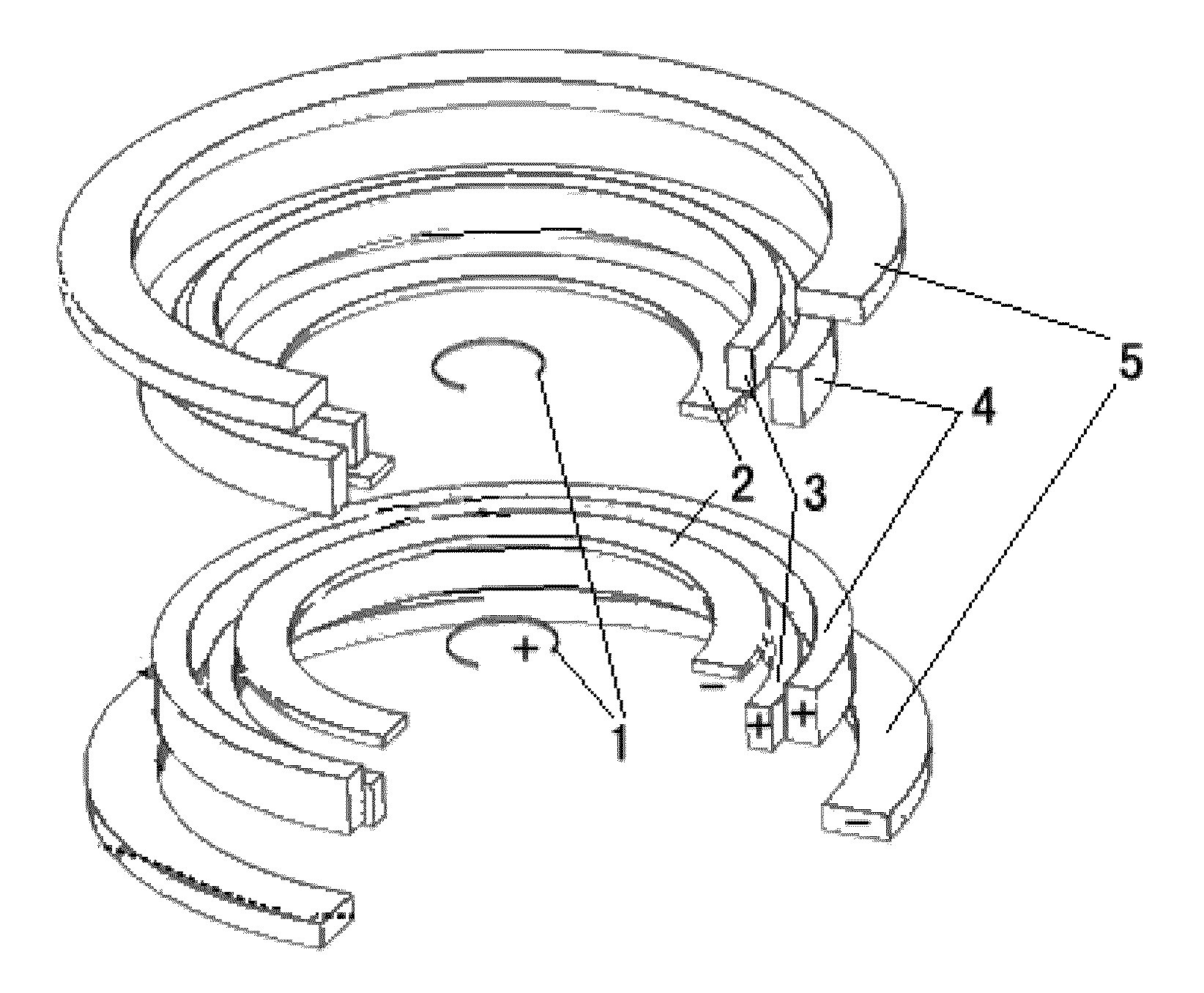
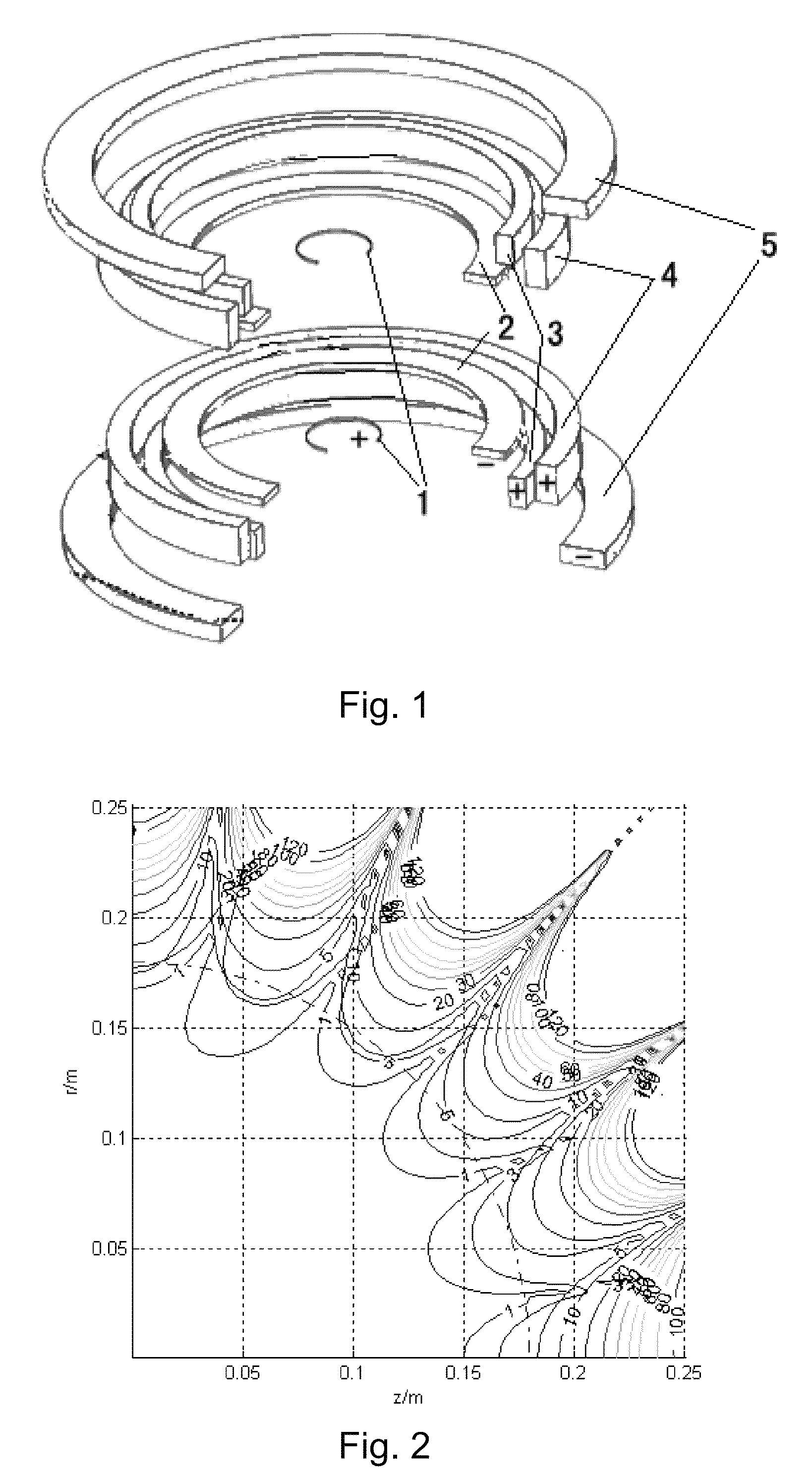
[0020]The structure of the open magnetic resonance magnet of this invention is shown in FIG. 1. This invention comprises five pairs of coils which are symmetric about the center, comprising shim coils 1, first main magnetic field coils 2, second main magnetic field coils 3, third main magnetic field coils 4 and shielding coils 5. The shim coils 1 are arranged closest to the central point, and the first main magnetic field coils 2, the second main magnetic field coils 3 and the third main magnetic field coils 4 are arranged in sequence outward, and the shielding coils 5 are arranged outermost. A main magnetic field is provided by the first main magnetic field coils 2, the second main magnetic field coils 3, and the third main magnetic field coils 4 together. The shim coils 13 compensate the magnetic field in the central region to improve magnetic field homogeneity of the mag...


PUM

PropertyMeasurementUnit
distanceaaaaaaaaaa
diameteraaaaaaaaaa
diameteraaaaaaaaaa

Abstract

A self-shield open magnetic resonance imaging superconducting magnet comprises five pairs of coils: shim coils, first main magnetic coils, second main magnetic coils, third main magnetic coils, and shielding coils. The five pairs of coils are symmetric about the center. The shim coils are arranged closest to the center point; the first main magnetic coils, the second main magnetic coils, the third main magnetic coils, and the shielding coils are arranged in sequence outside. The first main magnetic coils are connected with reverse current. The second and third main magnetic coils are connected with positive current for providing the main magnetic field strength. The shim coils are connected with positive current for compensating the magnetic field in the central region. The shielding coils are connected with reverse current for creating a magnetic field opposite to the main magnetic field for compensating the stray magnetic field in the space.

Description

CROSS-REFERENCE TO RELATED APPLICATIONS[0001]This application claims priority under 35 U.S.C. §371 to, and is a U.S. national phase application of, International Application No. PCT / CN2011 / 083970, filed Dec. 14, 2011, entitled “SELF-SHIELD OPEN MAGNETIC RESONANCE IMAGING SUPERCONDUCTING MAGNET,” which claims priority to Chinese Application No. 201110158077.8, filed Jun. 14, 2011, the disclosures of each is incorporated herein by reference in their entirety.FIELD OF THE INVENTION[0002]The present invention relates to a superconducting magnet used in the magnetic resonance imaging (MRI) field, and more particularly to an open superconducting magnet.TECHNICAL BACKGROUND[0003]MRI magnets for whole-body imaging require to achieve high homogeneous magnetic field in a large space, such as a magnetic field non-homogeneity less than 10 ppm (parts per million) in a range of 40 cm diameter spherical volume (DSV). Generally, magnet structures are in form of tunnel, and can provide high field an...

Claims


Application Information

Patent Timeline
Patent Type & Authority Patents(United States)
IPC IPC(8): G01R33/035G01R33/34G01R33/38G01R33/3815G01R33/421H01F6/06
CPCG01R33/34023G01R33/3806G01R33/3815H01F6/06G01R33/421
Inventor WANG, QIULIANGHU, XINNINGWANG, CHUNZHONGWANG, HUIYAN, LUGUANGDAI, YINMINGZHAO, BAOZHIWANG, JIANHUAXU, JIANYI
Owner INST OF ELECTRICAL ENG CHINESE ACAD OF SCI
Learn More