
Distance sensor system and method

a distance sensor and distance measurement technology, applied in the field of distance measurement, can solve the problems of inefficient ricocheting of conventional devices around an operating environment, waste of valuable consumables and battery capacity, and large size of typical distance measuring equipment, so as to achieve accurate distance measurements and short baseline

Active Publication Date: 2015-03-31
VORWERK & CO INTERHOLDING GMBH
View PDF74 Cites 60 Cited by
  • Summary
  • Abstract
  • Description
  • Claims
  • Application Information

AI Technical Summary

Benefits of technology

The present invention is a distance measuring system and method that uses a laser distance sensor. This sensor can accurately measure distances with a short baseline. This technology overcomes the shortcomings of conventional technology and provides a more versatile solution for applications that require accurate distance measurements.

Problems solved by technology

In that regard, primitive navigation systems cause conventional devices to ricochet around an operating environment inefficiently; these devices reactively carom off of obstacles and repeatedly re-visit areas that have already been treated, wasting valuable consumables and battery capacity.
In addition to the robot and automobile examples described above, for instance, a fork-lift operating in a warehouse may benefit from installation of accurate distance measuring systems, particularly since operator visibility may be restricted in many circumstances.
Typical distance measuring equipment is either too expensive to be practical for many applications or too large and cumbersome to be suitable for applications requiring a small form factor.
Two popular laser distance sensor (LDS) devices that have limited potential for use in vehicular or other applications, the SICK LMS 200, currently marketed by SICK AG, and the Hokuyo URG-04LX, currently marketed by Hokuyo Automatic Co., Ltd., both cost an order of magnitude more than the simplest home and commercial robot cleaners, making them unsuitable for such uses.
Additionally, these devices rely upon spinning mirrors for scanning operations, and consequently require attendant lenses and other optical components; the resulting large form factors and limited resolution and range tend to make most of these devices unsuitable for automotive or other large-scale applications.

Method used


Image

  • Distance sensor system and method
  • Distance sensor system and method
  • Distance sensor system and method

Examples


Embodiment Construction

Introduction

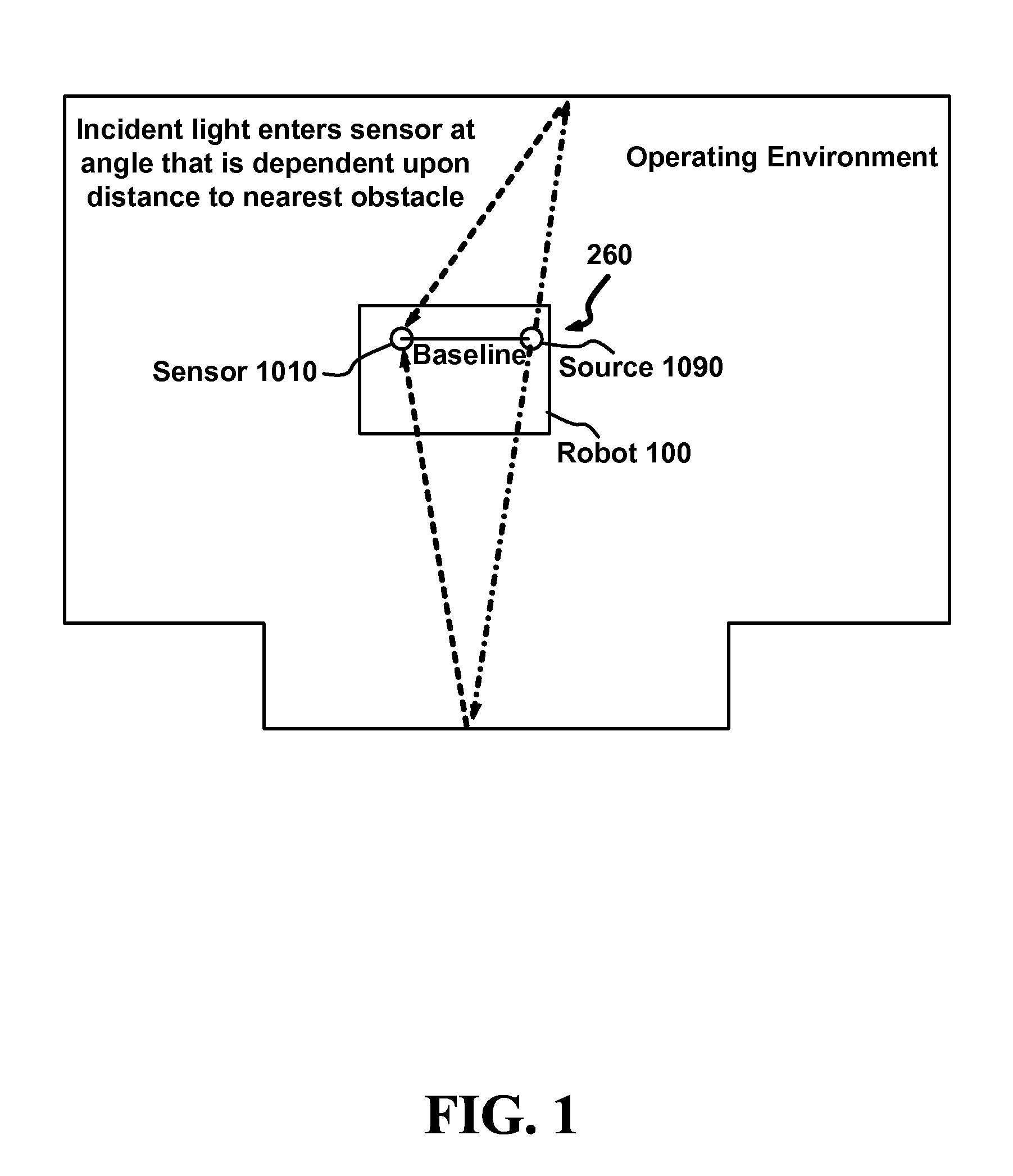
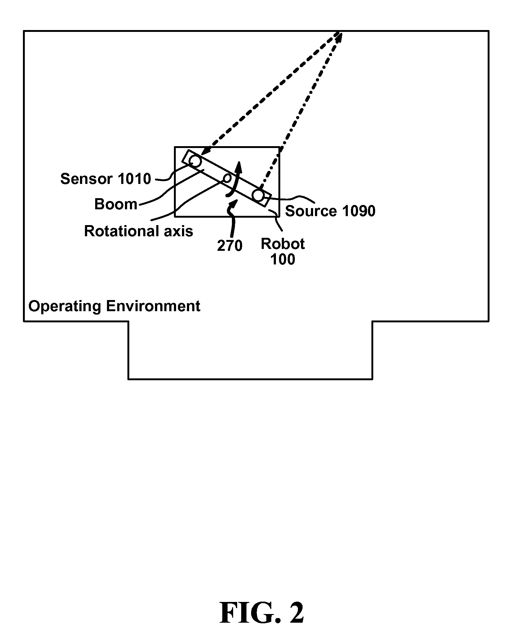
[0024]Some robotic systems, such as those disclosed in the related co-pending United States patent applications, for example, may use laser rangefinders to facilitate mapping and localization functionality. While manufacturing costs and power requirements associated with the various components represent impediments to development and deployment of low-cost, efficient robot platforms for consumer or commercial use, the foregoing applications and the present specification address solutions that make laser rangefinding technology practical in various contexts. In that regard, it is noted that laser distance sensor (LDS) technology has certain advantages that make it suitable for, among other implementations, indoor and outdoor mobile robot or automobile rangefinding applications.

[0025]While many sensor technologies (with varying degrees of complexity) may be utilized for acquiring distance data, LDS systems efficiently provide data in readily useable form. For example, an L...


PUM


Abstract

A distance measuring system and method employing a laser distance sensor may have utility in various applications. In accordance with one aspect of the present invention, a laser distance sensor may acquire accurate distance measurements with a short baseline.

Description

CROSS-REFERENCE TO RELATED APPLICATIONS[0001]The present application is a continuation in part of co-pending U.S. patent application Ser. No. 11 / 515,022, entitled “MULTI-FUNCTION ROBOTIC DEVICE,” filed Sep. 1, 2006, and a continuation in part of co-pending U.S. patent application Ser. No. 11 / 515,100, entitled “LOCALIZATION AND MAPPING SYSTEM AND METHOD FOR A ROBOTIC DEVICE,” filed Sep. 1, 2006, the disclosures of which are incorporated herein by reference in their entireties.BACKGROUND[0002]1. Field of the Invention[0003]Aspects of the present invention relate generally to the field of distance measuring, and more particularly to a distance measuring system and method employing a laser distance sensor having utility in various applications.[0004]2. Description of Related Art[0005]Automatic or autonomous devices (i.e., robotic devices or robots) that can be used for home and commercial applications, such as cleaning, often must be operative to navigate around an environment with no, ...

Claims


Application Information

Patent Timeline
Patent Type & Authority Patents(United States)
IPC IPC(8): G05B15/02G06G7/78G01C3/00G05B19/042G01S7/481G01S7/497G01S17/42G01S17/48
CPCG01S7/4813G01S17/42G01S17/48G01S7/4817G01S2007/4977G01S7/497
Inventor SHAH, PANKAJKONOLIGE, KURTAUGENBRAUN, JOEDONALDSON, NICKFIEBIG, CHARLESLIU, YUMINGKHAN, HASSAAN MOINPINZARRONE, JOSEPHSALINAS, LEOTANG, HUATAYLOR, RAFAEL
Owner VORWERK & CO INTERHOLDING GMBH
Learn More