Air-source
heat pump systems are generally less efficient than
geothermal heat pump systems, but the purchase / installation costs of an air-
source system is generally less expensive than the purchase / installation costs of a geothermal system.
However, the operational and maintenance costs of
geothermal heat pump systems (with a DX system typically being the most advantageous) are generally less than those of an air-source heat pump.
Consequently, the
moisture from the air freezes, creating a layer of
frost / ice.
As the
frost / ice builds up, the fan-augmented
airflow across the exterior finned heat exchange tubing becomes impaired and adequate operational efficiencies are lost, since not enough heat can be acquired from the exterior air to provide design level heat to the
interior space.
Such an instantaneous shift of the
reversing valve, to place the air-source heat pump system in a defrost cycle (or actually into the cooling mode), is noisy and is hard on the compressor (contributing to accelerated
wear and tear and / or to eventual compressor failure), and simultaneously effectively requires a reverse directional flow of the refrigerant fluid within both the exterior and the interior heat exchangers.
Such a reverse refrigerant directional flow also modifies the pre-existing optimum refrigerant fluid charge amount in the respective interior and exterior heat exchangers, requiring additional inefficient operational time to re-establish the optimum respective charges once the defrost cycle is over and the
reversing valve is switched back into a normal heating mode position.
Even worse, during a typical defrost cycle, since the air-source heat pump system is actually operating in the cooling mode, heat from the interior air is being removed and transferred into the exterior heat exchanger to help melt the frost / ice build-up.
Such cooling mode operation in the winter, coupled with a requirement for supplemental heat, is both expensive for the owner of the structure and is expensive for the
electric utility company supplying power, as multiple air-source heat pumps in the area tend to create “peaking” concerns for the utility.
Such peaking issues require the
electric utility to either provide extra
generating capacity for only relatively short periods of time, or to pay other electric providers for their extra power availability, both of which are very expensive.
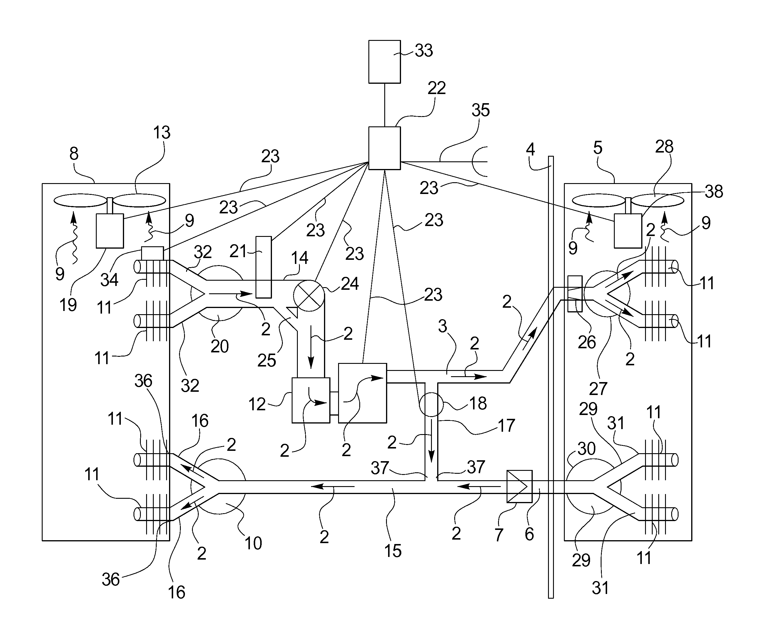
While the subject defrost disclosure in the '129 patent will work, the design is such that: hot gas refrigerant is not disclosed as being supplied into the exterior heat exchanger, in the heating / defrost mode, through larger than normal
liquid phase refrigerant transport lines, which will impair defrost abilities and will disadvantageously increase defrost
period timing; there is no restriction shown in the exiting vapor transport line from the exterior heat exchanger, which will impair both defrost ability and will disadvantageously increase defrost
period timing; there is no disclosure that any extra refrigerant charge is required, which will impair optimum system operation; an optimum
sizing of the hot gas line by-passing the indoor heat exchanger is not disclosed, which makes it impossible to know how to optimize defrost results; and some unidentified amount of the hot gas by-passing the indoor heat exchanger is being directed into the accumulator, thereby not affording full optimum utilization of the by-passing hot gas to provide heat to interior air or to melt the frost / ice on the heat exchange tubing of the exterior heat exchanger, and thereby increasing defrost cycle operational time (which impairs both interior
heat supply abilities and defrost cycle operational timing), and which unnecessarily requires hot gas to be directed and bubbled into the accumulator.
's disclosure (with the defrost cycle operating only when the frost / ice build-up is relatively thick on the exterior heat exchanger's
heat transfer tubing), customarily longer periods of defrost cycle operation may be required, resulting in more interior
heat losses during the defrost cycle, and resulting in more condensation issues with the hot gas refrigerant used to melt the frost / ice in the outdoor heat exchange tubing (which is an additional likely reason Cann, et al. requires some hot gas to be diverted to the accumulator).
Further, by diverting the hot
discharge gas into both the exterior heat exchanger and the accumulator during the defrost mode of operation, there will likely be an insufficient amount of hot gas available to supply an optimum amount of heat to the interior
air handler during a defrost cycle; and the subject design makes no mention of a timed operation of the
fan in the exterior heat exchanger, and, of necessity as disclosed, will impose a power peaking period upon the system as a result of the defrost cycle operation as disclosed therein.
Park also explains that, in a case where there is an excessive quantity of frost, a three-way valve supplies the hot gas to the exterior heat exchanger only at 20-30 second intervals, during which interior heating is interrupted, so that it is difficult for the user to recognize that the heating mode has actually been fully stopped during those 20-30 second intervals (see page 5, paragraphs 0070 and 0071).
Again, while Park's design will work, Park does not provide a full unrestricted 100% hot gas flow into the exterior heat exchanger, through larger than normal
liquid phase refrigerant transport lines, since the hot gas primarily goes through a conventional (small)
distributor (Park's number 16) and (small) distribution tubes (Park's number 33); Park does not disclose a preferable optimum size of the hot gas by-pass line to the exterior heat exchanger; and Park provides no restriction in the vapor line exiting the exterior heat exchanger, which disadvantageously increases requisite defrost time, requiring more time for the interior
air handler to remain totally un-functional, as Park does not simultaneously provide any interior heat (via simultaneously supplying hot gas to the interior
air handler) while operating in his primary defrost cycle.
Further, testing has indicated that, via switching from defrost to heating every 20-30 seconds, the
heat supply ability of the interior air handler is materially impaired, since normal
heat supply levels via the interior air handler are lost and take much longer than 20-30 seconds to build back up after the refrigerant flow to the interior air handler has been totally
cut off during the preceding 20-30 second period.
Further, in Park's design, there is no disclosure that any extra refrigerant charge is required, which will impair optimum system operation since the addition of extra refrigerant transport lines, as taught by Park, will require some extra charge for optimum system performance; an optimum
sizing of the hot gas line by-passing the indoor heat exchanger is not disclosed, which makes it impossible to know how to optimize defrost results; there is no mention of a timed operation of the
fan in the exterior heat exchanger, and, of necessity as disclosed, will impose a power peaking period upon the system as a result of the defrost cycle operation as disclosed therein; and the periodic use of a liquid
receiver (Park's 43) is required, which is an extra cost and expense that may be unnecessary.

