Fiber optic connectors and structures for optical fibers and methods for using the same

a technology of optical fiber connectors and fiber optic connectors, applied in the direction of optical elements, instruments, manufacturing tools, etc., can solve the problems of not being suitable for longer distance optical networks, unable to meet the requirements of optical networks, and complicated termination or connectorization of conventional glass optical fibers, etc., to achieve the effect of convenient and quick preparation

Active Publication Date: 2015-04-07
CORNING INC
View PDF18 Cites 1 Cited by
  • Summary
  • Abstract
  • Description
  • Claims
  • Application Information

AI Technical Summary

Benefits of technology

[0007]Embodiments of the disclosure are directed to fiber optic connectors and other structures that can be easily and quickly prepared by the craft for termination and / or connectorization in the field. More specifically, at least in some embodiments, the fiber optic connectors and other structures disclosed are intended for use with glass optical fibers having a large core. Methods of using the fiber optic connectors and other structures are also disclosed. According to some embodiments, the methods disclosed allow “rough cutting” of the optical fibers with a buffer layer thereon, and optically coupling such fiber to another component, for example to a detector in a receiver or to a light source in a transmitter, or to another optical fiber.

Problems solved by technology

However, POF has limitations such as not being suitable for longer distance optical networks because of high attenuation and limited bandwidth.
However, terminating or connectorizing conventional glass optical fibers is more complicated than terminating POF because it usually requires special cleaving tools and / or stripping tools for preparing the optical fibers.
Moreover, conventional terminations or splicing of glass optical fibers may require a skilled technician and / or specialized equipment.
Field-terminated optical fiber connectors having a mechanical splice are available to the craft but are not typically used for short distance optical networks even though they are suitable for these applications.

Method used


Image

  • Fiber optic connectors and structures for optical fibers and methods for using the same
  • Fiber optic connectors and structures for optical fibers and methods for using the same
  • Fiber optic connectors and structures for optical fibers and methods for using the same

Examples


example

[0061]This design is optimized for an operating wavelength of approximately 665 nm, however the same principle can also be employed at different wavelengths, by a suitable choice of materials and components.

[0062]In the first type of connection, namely from an optical source to an optical fiber, the optical source can be a Vettical-Cavity Surface-Emitting Laser, emitting at a wavelength of approximately 665 nm, such as, for example, Firecomms model RVM665T-100 manufactured by Firecomms Ltd. The optical source may have a lateral dimension (diameter or side) of the emitting aperture not exceeding 20 m, and a divergence half-angle not exceeding 25 degrees.

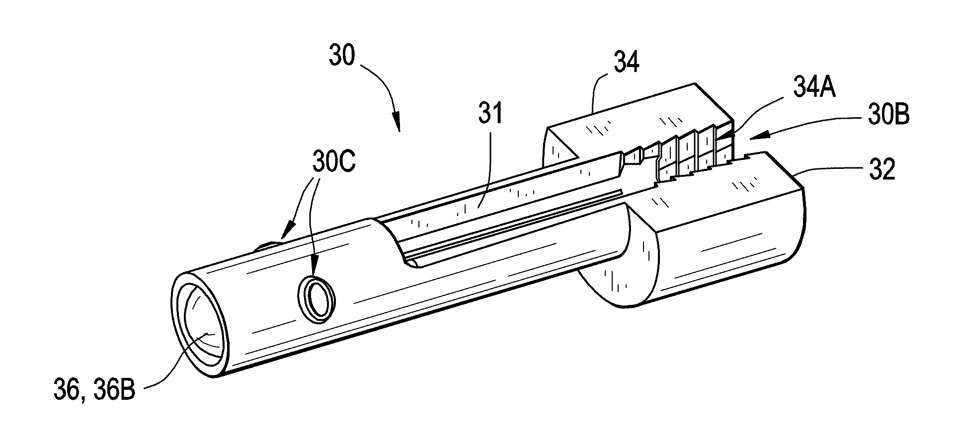
[0063]In this embodiment the optical fiber 10 has a silica core with a diameter of 200 μm and has numerical aperture (NA) of 0.37.

[0064]The first lens 130, which is part of the optical transmitter, transforms the diverging optical beam emitted by the VCSEL into an essentially collimated beam. The second lens 36B, which is part of the ...


PUM

PropertyMeasurementUnit
core diameteraaaaaaaaaa
Young's modulusaaaaaaaaaa
diameteraaaaaaaaaa

Abstract

In one embodiment, a device comprises at least one ferrule having a bore, the bore extending from a rear of the ferrule toward a front of the ferrule, wherein the bore is sized to receive an optical fiber with a buffer at a rear end face of the ferrule, wherein the front end of the ferrule includes an optical component.

Description

[0001]This application claims the benefit of priority of U.S. Provisional Application Ser. No. 61 / 303,486 filed Feb. 11, 2010.BACKGROUND[0002]1. Field[0003]The disclosure is directed to fiber optic connectors along with other structures and methods for using the same. More specifically, the disclosure is directed to fiber optic connectors and other structures suitable for use with large core optical fibers and methods for using these connectors.[0004]2. Technical Background[0005]Optical fiber is increasingly being used for a variety of applications, including but not limited to broadband voice, video, and data transmission. Optical fibers may be formed from different types of materials such as plastic or glass depending on the application. Typically, plastic optical fibers (POF) have been used in short distance optical networks since they are relatively easy to terminate by untrained personnel. However, POF has limitations such as not being suitable for longer distance optical netwo...

Claims


Application Information

Patent Timeline
Patent Type & Authority Patents(United States)
IPC IPC(8): G02B6/36G02B6/32G02B6/38
CPCG02B6/3833G02B6/3853G02B6/325G02B6/3834G02B6/3849G02B6/3858G02B6/25G02B6/4292Y10T29/49826
Inventor FORTUSINI, DAVIDE DOMENICOISENHOUR, MICAH COLENKNECHT, DENNIS MICHAELLUTHER, JAMES PHILLIP
Owner CORNING INC
Why Eureka
Try Eureka