Electrosurgical instrument and method for producing an electrosurgical instrument

a technology of electrosurgical instruments and electrosurgical instruments, applied in the field of surgical instruments, can solve the problem of low specific resistance of copper and achieve the effect of suitable dimensions and easy and efficient manufacturing

Inactive Publication Date: 2015-04-07
ERBE ELEKTROMEDIZIN GMBH
View PDF10 Cites 3 Cited by
  • Summary
  • Abstract
  • Description
  • Claims
  • Application Information

AI Technical Summary

Benefits of technology

[0009]The disclosed embodiments relate to an electrosurgical instrument as well as to a method for producing an electrosurgical instrument. It is the object of the disclosed embodiments to provide an electrosurgical device that is safe, has suitable dimensions, and is easily and efficiently manufactured.
[0011]It is a particular advantage of the disclosed embodiments that an electrically conductive exterior skin, i.e., the conductive foil of the probe tube, is used as the electrical conductor or as the conductor path. Consequently, the electrical lead can be provided for at least one electrode, preferably for the proximal electrode, without requiring the electrical lead be taken into consideration when dimensioning the probe tube. Providing the conductive foil results in only a minimal additional increase of the wall thickness, so that relatively small probes can be developed. Compared with the prior art, it is not necessary to perforate the probe tube in order to produce an appropriate electrical pathway. Therefore, the process of manufacturing an electrosurgical instrument in accordance with the invention is also relatively simple.
[0014]Theoretically, the individual adjacent tracks of the conductive foil could be arranged so as to overlap—at least in sections—along the longitudinal direction of the probe tube. Consequently, an essentially tubular conductive path would be formed that only minimally affects the flexibility of the probe tube and exhibits only a minimal inductive resistance. Preferably, the adjacent tracks of conductive foil are arranged in longitudinal direction of the probe tube at a distance from each other so that no overlapping occurs. Any overlapping represents an additional thickening of the diameter of the electrosurgical instrument. Due to the width of the tracks of the conductive foil, the inductive resistance is tolerable.
[0015]The instrument may include an insulator layer that covers—at least in sections—the conductive foil in order to fixate the foil. Preferably, the resultant cross-section shows an arrangement that is configured from the inside of the probe tube toward the outside as follows: wall of the probe tube, conductive foil, insulator layer. The insulator layer may be extremely thin-walled and insulates the conductor path formed by the conductive foil against the outside region. Furthermore, the insulator protects the conductive foil against outside influences and is able to hold the conductive foil in place. The insulator layer may be produced of a material that only minimally affects the flexibility of the probe tube and thus the electrosurgical instrument.

Problems solved by technology

Also, copper exhibits a low specific resistance.

Method used


Image

  • Electrosurgical instrument and method for producing an electrosurgical instrument
  • Electrosurgical instrument and method for producing an electrosurgical instrument

Examples


Embodiment Construction

[0021]In the description hereinafter, the same reference signs will be used for parts that are the same or that have the same function.

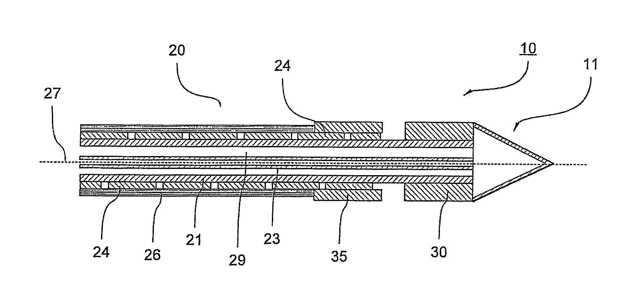
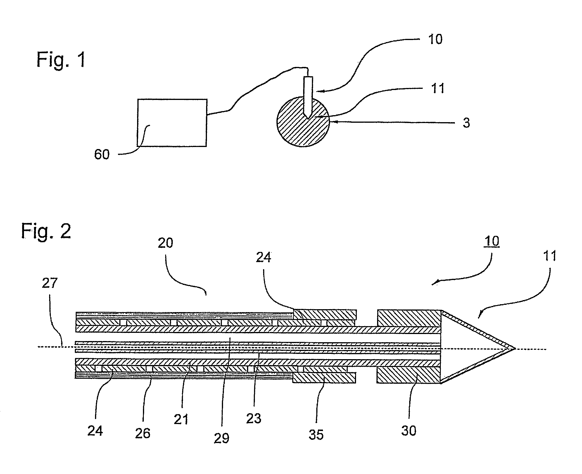
[0022]FIG. 1 shows an RF surgical device for devitalizing tissue. An ablation probe 10 is connected via a supply tube and several cables with a supply device 60. The ablation probe 10 is inserted into a tissue 3 that is to be devitalized by means of an RF current, the current being applied through the ablation probe. For this, electrodes, i.e., a distal electrode 30 and a proximal electrode 35, shown in FIG. 2, arranged on the ablation probe 10 are connected with an RF generator in the supply unit 60. In order to completely devitalize the tissue 3, it is necessary to cool the ablation probe 10 in at least some sections in order to avoid a carbonization of the tissue contacted by the ablation probe 10. Therefore, the ablation probe 10, in accordance with an embodiment of the invention, comprises a cooling system that is fed by the supply unit 60.

[0023...


PUM

PropertyMeasurementUnit
RF voltageaaaaaaaaaa
electricalaaaaaaaaaa
conductiveaaaaaaaaaa

Abstract

An electrosurgical instrument including a probe tube for transporting fluid, at least one electrode for devitalizing tissue, and at least one conducting foil electrical lead arranged along the longitudinal axis of the probe tube for providing a high frequency (RF) voltage at the electrode. A method of producing an electrosurgical instrument, including applying a conductive foil to a probe tube that extends along the longitudinal axis of the probe tube, and providing at least one electrode on the probe tube, wherein the electrode electrically connects to the conductive foil.

Description

CROSS-REFERENCE TO RELATED APPLICATIONS[0001]This application claims priority to PCT / EP2010 / 003595, filed Jun. 16, 2010 and published as WO 2011 / 003503, which claims priority to DE102009032065.2, filed Jul. 7, 2009 and also to DE 102009048312.8, filed Oct. 5, 2009.FIELD OF THE INVENTION[0002]The disclosed embodiments relate to surgical instruments, and more particularly to electrosurgical instruments.BACKGROUND OF THE INVENTION[0003]In high-frequency (RF) surgery it is known to devitalize tissue in a targeted manner by means of the application of RF current. Such an operation can be performed with the use of a monopolar or bipolar instrument. With the use of a monopolar instrument, the current path usually leads from the electrosurgical instrument via the tissue to be treated to the neutral electrode. With the use of a bipolar instrument, the instrument is designed to have two sections that are electrically insulated from each other so the current path extends from a first section o...

Claims


Application Information

Patent Timeline
Patent Type & Authority Patents(United States)
IPC IPC(8): A61B18/18A61B18/00A61B18/02A61B18/14A61N1/06
CPCA61N1/06A61B18/1477A61B18/1492A61B2018/00023A61B2018/00047A61B2018/00053A61B2018/0231A61B2018/0262A61B2562/222Y10T29/49117
Inventor BESCH, HANSJOERG BJOERNSCHWAHN, BRITTA
Owner ERBE ELEKTROMEDIZIN GMBH
Why Eureka
Try Eureka