Method for determining the cut quality of a laser cutting process using a simulation program

a laser cutting process and simulation program technology, applied in the direction of design optimisation/simulation, manufacturing tools, instruments, etc., can solve problems such as unreachable, and achieve the effect of determining the cut quality

Inactive Publication Date: 2015-04-07
FRAUNHOFER GESELLSCHAFT ZUR FOERDERUNG DER ANGEWANDTEN FORSCHUNG EV +1
View PDF6 Cites 0 Cited by
  • Summary
  • Abstract
  • Description
  • Claims
  • Application Information

AI Technical Summary

Benefits of technology

The present invention provides a method for assessing the quality of a laser cutting process by using specific parameters for the material being cut, the laser cutting machine, and the process parameters. The method can also include adjusting the roughness of the cut face.The method includes performing temporal modulations on the parameters to improve productivity and optimize ridge morphology. This modulation can be used to generate defined structures, minimize ridge structures, and form logos or images on the cut face.

Problems solved by technology

This method is not performed on an real laser cutting machine.

Method used


Image

  • Method for determining the cut quality of a laser cutting process using a simulation program
  • Method for determining the cut quality of a laser cutting process using a simulation program
  • Method for determining the cut quality of a laser cutting process using a simulation program

Examples


Embodiment Construction

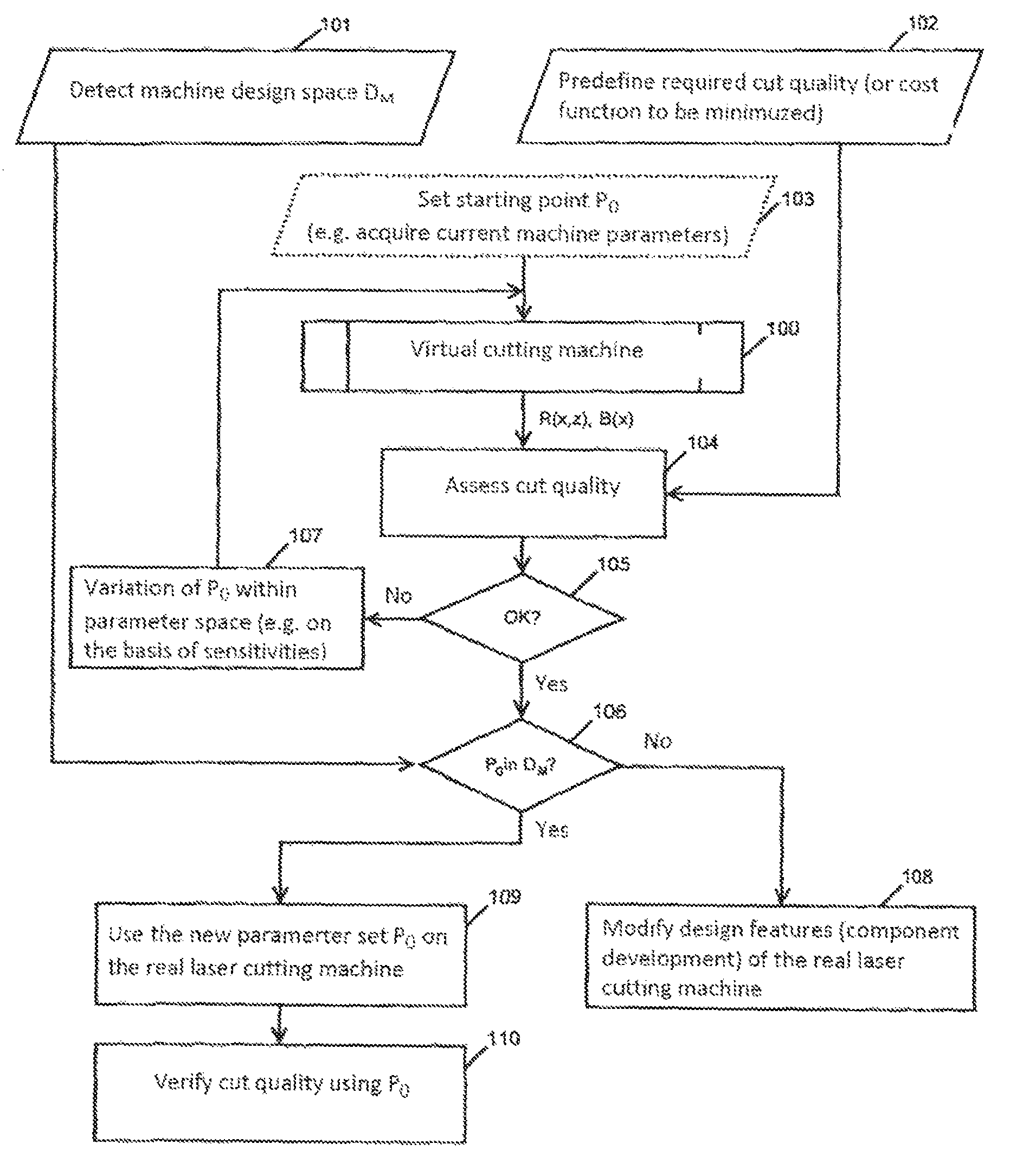
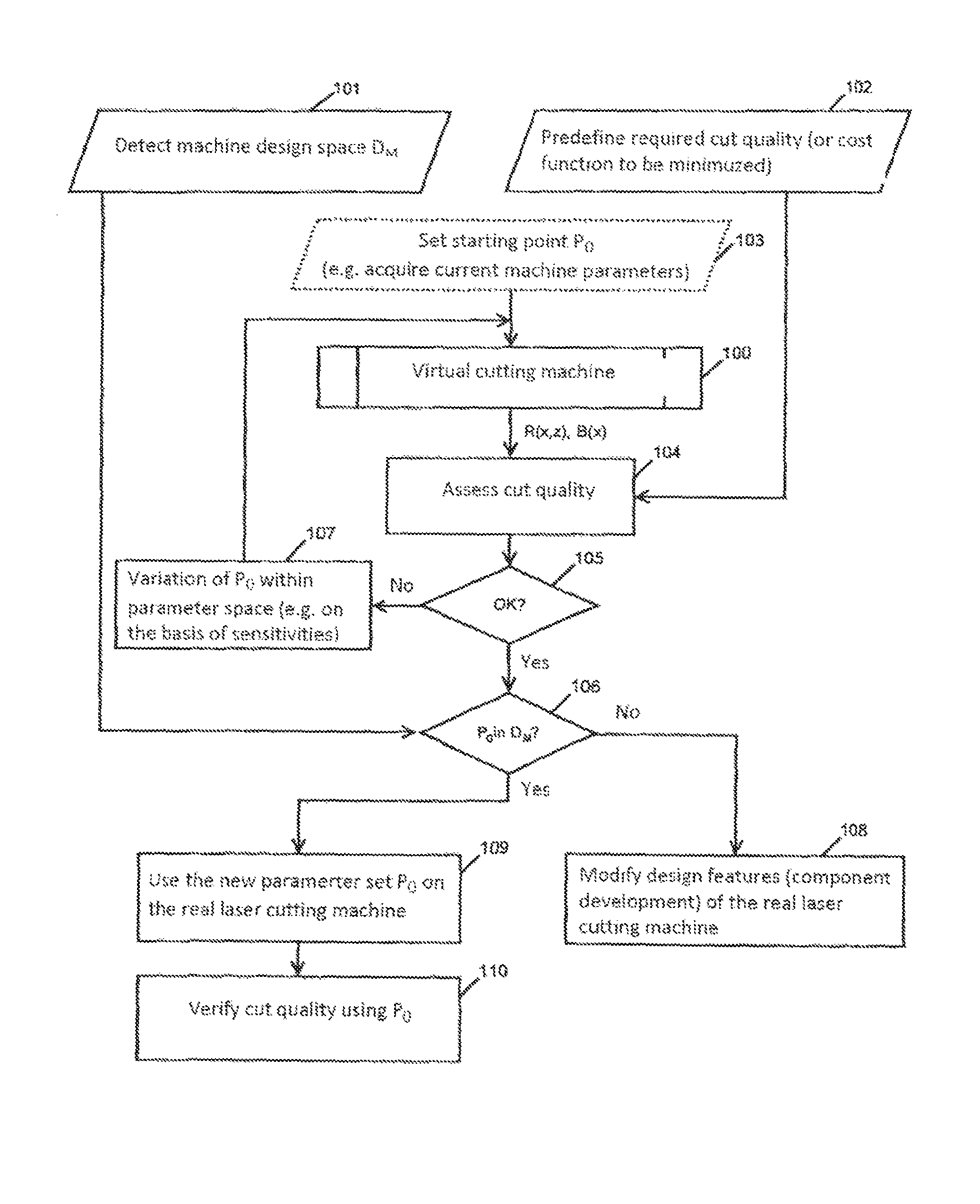
[0093]The method according to the invention, as shown in the diagram, employs a virtual cutting machine, which is designated with the reference character 100. For the implementation of the method, for one the design space DM is acquired, step 101, and secondly, the required cut quality entered, step 102. A cost function to be minimized can be specified in step 102 as well.

[0094]To start the virtual cutting machine 100, a start point P0 is specified in step 103, for example by detecting the machine parameters of a current, real cutting machine. The set of values of P0 is selected from the parameter space P, as is defined in greater detail above.

[0095]The simulation program is started by creating a virtual cut with the virtual cutting machine, which can be based on real values. The simulation program outputs a result of the cutting that includes the spatial distribution of the ridge amplitude R(x,z) on the cut face and the spatial distribution of the burr B(x) at the lower edge of the...


PUM

PropertyMeasurementUnit
Sensitivityaaaaaaaaaa

Abstract

The application relates to a method for determining the cut quality of a laser cutting process, said quality being assessed on the basis of the formation of solidification ridges along the cut face and / or burr formation on the lower edge of the cut face. In said method, a virtual laser cutting machine in a simulation program can be virtually operated with a set of values P0 from a parameter space P.; In a step a), the parameter set P0 is entered in the virtual cutting machine (103), then in step b), a cut is made in the virtual workpiece by calculating, from partial differential equations with initial and boundary values, the progression of the melt film thickness over time and the position of the melt front at the apex of the cutting front according to the depth of the cut and the time, and then in step c), the spatial distribution of the ridge amplitude on the cut face is specified by projecting the progression of the absorption front onto the cut face and / or a spatial distribution of the burr is calculated from the progression of the melt film thickness over time and the discharge speed on the lower edge of the cut face, and in step d), a virtual cut quality is provided (104) for further analysis.

Description

BACKGROUND OF THE INVENTION[0001]The present invention relates to a method for determining the cut quality of a laser cutting process, which is assessed based on the formation of solidification ridges along the cut face and / or burr formation at the bottom edge of the cut face, where in a simulation program a virtual laser cutting machine is provided that can be operated virtually using a set of values P0 from a parameter space P.[0002]Laser cutting is an established separation process. Among the laser-aided manufacturing methods, it takes the leading position in industrial applications. From the user's perspective, high productivity with high quality is demanded for such manufacturing methods.[0003]Currently, high quality CO2-Lasers (10μ-emitters) with a radiation wavelength of approx. 10 μm and with a laser power of 1-6 kW are employed industrially for laser cutting in the field of macro applications for sheet metal thicknesses ranging from 1 mm to 30 mm. In addition, new laser sou...

Claims


Application Information

Patent Timeline
IPC IPC(8): G06F17/50B23K26/06B23K26/38
CPCB23K26/06B23K26/38G06F17/5009G06F2217/78G06F2217/80G06F30/20G06F2119/06G06F2119/08
Inventor SCHULZ, WOLFGANGSCHUETTLER, JENSVOSSEN, GEORGENIESSEN, MARKUS
Owner FRAUNHOFER GESELLSCHAFT ZUR FOERDERUNG DER ANGEWANDTEN FORSCHUNG EV
Why Eureka
Try Eureka