Assessing the location and performance of replacement heart valves

a heart valve and location technology, applied in the field of assessing the location and performance of replacement heart valves, can solve the problems of heart failure, stroke, heart attack, adverse reactions to anesthesia medications, and high invasiveness of valve replacement surgery

Active Publication Date: 2015-04-14
BOSTON SCI SCIMED INC
View PDF917 Cites 331 Cited by
  • Summary
  • Abstract
  • Description
  • Claims
  • Application Information

AI Technical Summary

Problems solved by technology

Valve replacement surgery is a highly invasive operation with significant concomitant risk.
Risks include bleeding, infection, stroke, heart attack, arrhythmia, renal failure, adverse reactions to the anesthesia medications, as well as sudden death.
PVT's device suffers from several drawbacks.
Deployment of PVT's stent is not reversible, and the stent is not retrievable.
This is a critical drawback because improper positioning too far up towards the aorta risks blocking the coronary ostia of the patient.
Furthermore, a misplaced stent / valve in the other direction (away from the aorta, closer to the ventricle) will impinge on the mitral apparatus and eventually wear through the leaflet as the leaflet continuously rubs against the edge of the stent / valve.
Another drawback of the PVT device is its relatively large cross-sectional delivery profile.
The PVT system's stent / valve combination is mounted onto a delivery balloon, making retrograde delivery through the aorta challenging.
An antegrade transseptal approach may therefore be needed, requiring puncture of the septum and routing through the mitral valve, which significantly increases complexity and risk of the procedure.
Very few cardiologists are currently trained in performing a transseptal puncture, which is a challenging procedure by itself.
Standard self-expanding systems have very poor accuracy in deployment, however.
It is therefore often impossible to know where the ends of the stent will be with respect to the native valve, the coronary ostia and the mitral valve.
Visualization prior to final and irreversible deployment cannot be done with standard self-expanding systems, however, and the replacement valve is often not fully functional before final deployment.
Another drawback of prior art self-expanding replacement heart valve systems is their lack of radial strength.
However when the stent has a valve fastened inside it, as is the case in aortic valve replacement, the anchoring of the stent to vessel walls is significantly challenged during diastole.
Moreover, a self-expanding stent without sufficient radial force will end up dilating and contracting with each heartbeat, thereby distorting the valve, affecting its function and possibly migrating and dislodging completely.
Simply increasing strut thickness of the self-expanding stent is not a practical solution as it runs the risk of larger profile and / or plastic deformation of the self-expanding stent.
While providing for an aortic approach, devices described in the Garrison patent application suffer from several drawbacks.
First, the stent portion of the device is delivered across the native valve as a single piece in a single step, which precludes dynamic repositioning of the stent during delivery.
Stent foreshortening or migration during expansion may lead to improper alignment.
This increases an immediate risk of blocking the coronary ostia, as well as a longer-term risk of migration of the device post-implantation.
Tissue may protrude through these gaps, thereby increasing a risk of improper seating of the valve within the stent.

Method used


Image

  • Assessing the location and performance of replacement heart valves
  • Assessing the location and performance of replacement heart valves
  • Assessing the location and performance of replacement heart valves

Examples


Embodiment Construction

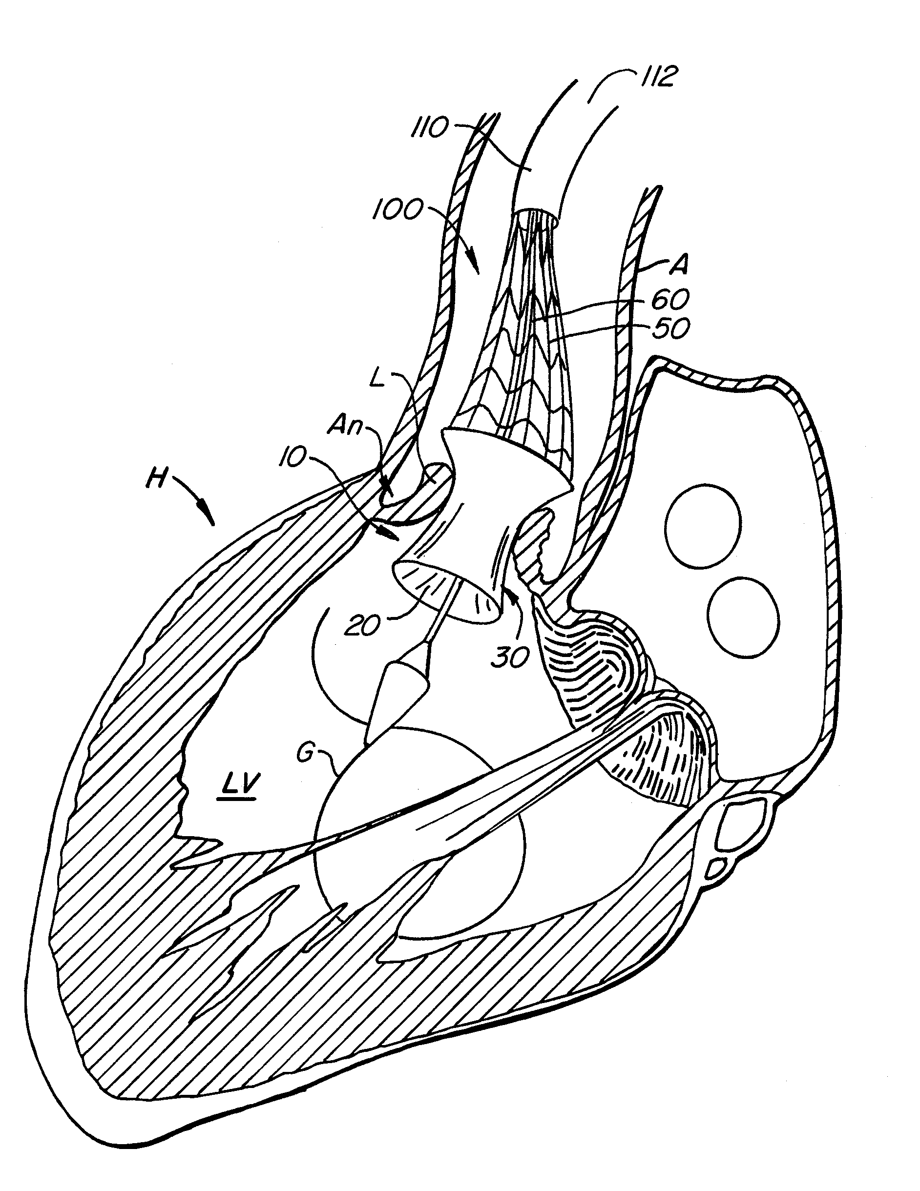
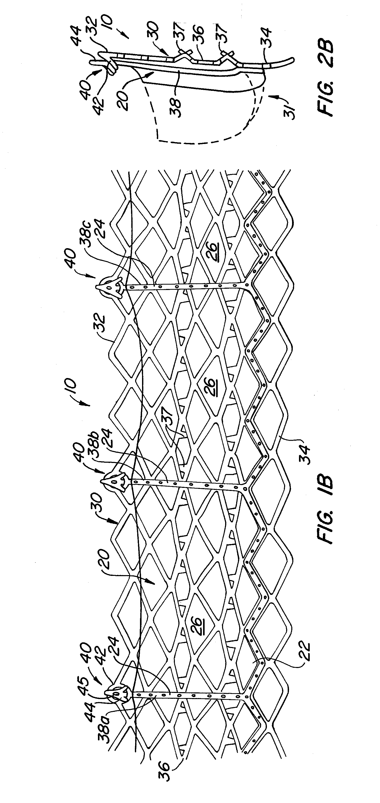
[0088]With reference now to FIGS. 1-4, a first embodiment of replacement heart valve apparatus in accordance with the present invention is described, including a method of actively foreshortening and expanding the apparatus from a delivery configuration and to a deployed configuration. Apparatus 10 comprises replacement valve 20 disposed within and coupled to anchor 30. FIGS. 1 schematically illustrate individual cells of anchor 30 of apparatus 10, and should be viewed as if the cylindrical anchor has been cut open and laid flat. FIGS. 2 schematically illustrate a detail portion of apparatus 10 in side-section.

[0089]Anchor 30 has a lip region 32, a skirt region 34 and a body region 36. First, second and third posts 38a, 38b and 38c, respectively, are coupled to skirt region 34 and extend within lumen 31 of anchor 30. Posts 38 preferably are spaced 120° apart from one another about the circumference of anchor 30.

[0090]Anchor 30 preferably is fabricated by using self-expanding pattern...


PUM


Abstract

Methods and devices for assessing the operation of a replacement heart valve. The method includes endovascularly delivering a replacement heart valve to a vicinity of a heart valve in an unexpanded configuration, and assessing the operation of the replacement heart valve in the vicinity of the heart valve before fully expanding the replacement heart valve. Methods and devices for assessing the location of a replacement heart valve. The method includes endovascularly delivering a replacement heart valve to a vicinity of the heart valve in an unexpanded configuration, expanding the replacement heart valve to a partially deployed configuration, and assessing the location of the replacement heart valve in the vicinity of the heart valve before fully expanding the replacement heart valve.

Description

CROSS-REFERENCE[0001]This application is a continuation-in-part of application Ser. No. 10 / 746,280, filed Dec. 23, 2003, now U.S. Pat. No. 8,840,663 which is incorporated herein by reference in its entirety. This application is also a continuation-in-part of application Ser. No. 10 / 971,535, filed Oct. 21, 2004 now U.S. Pat. No. 8,343,213; which is a continuation-in-part of application Ser. No. 10 / 746,240, filed Dec. 23, 2003 now abandoned, which are incorporated herein by reference in their entirety.BACKGROUND OF THE INVENTION[0002]Heart valve surgery is used to repair or replace diseased heart valves. Valve surgery is an open-heart procedure conducted under general anesthesia. An incision is made through the patients's sternum (sternotomy), and the patients's heart is stopped while blood flow is rerouted through a heart-lung bypass machine.[0003]Valve replacement may be indicated when there is a narrowing of the native heart valve, commonly referred to as stenosis, or when the nati...

Claims


Application Information

Patent Timeline
Patent Type & Authority Patents(United States)
IPC IPC(8): A61F2/06A61F2/24
CPCA61F2/2418A61F2/2439A61F2/2433A61F2/2436A61F2220/0016A61F2220/005A61F2220/0058A61F2220/0075A61F2230/005A61F2230/0054A61F2230/0065A61F2230/0078
Inventor SALAHIEH, AMRBRANDT, BRIAN D.MOREJOHN, DWIGHT P.HAUG, ULRICH R.DUERI, JEAN-PIERREVALENCIA, HANS F.GESHLIDER, ROBERT A.KROLIK, JEFF
Owner BOSTON SCI SCIMED INC
Why Eureka
Try Eureka