Online real-time cutter breakage monitoring method

a real-time, monitoring method technology, applied in computer control, program control, instruments, etc., can solve the problems of low production efficiency, affecting the life of machine tools, and jeopardizing the safety of operators, so as to enhance speed and accuracy, and quickly and accurately determine the occurrence of cutter breakage.

Inactive Publication Date: 2015-04-14
CHUNG YUAN CHRISTIAN UNIVERSITY
View PDF5 Cites 6 Cited by
  • Summary
  • Abstract
  • Description
  • Claims
  • Application Information

AI Technical Summary

Benefits of technology

[0009]Therefore, it is a primary objective of the present invention to provide an online real-time cutter breakage monitoring method that uses a vibration signal capturing module and a monitoring subsystem to capture the cutting vibration acceleration signals in three consecutive time periods for an analysis, and compare the maximum values and the average values of the cutting vibration acceleration signals in the three consecutive time periods with one another, and the average value of the last time period is compared with an idling critical value, and the two-stage synchronous determination method can quickly and accurately determine the occurrence of a cutter breakage and enhance the speed and accuracy of the determinations significantly.
[0010]Another objective of the present invention is to provide an online real-time cutter breakage monitoring method, such that the system can be shut down immediately when a cutter breakage occurs, and a warning unit is installed and provided for alerting operators at site to take immediate actions to enhance the manufacturing efficiency effectively.
[0011]To achieve the foregoing objectives, the present invention provides an online real-time cutter breakage monitoring method using a vibration signal capturing module and a monitoring subsystem, and the monitoring subsystem is electrically coupled to the vibration signal capturing module, and the method comprises the steps of: capturing a plurality of cutting vibration acceleration signals when a CNC machine tool performs a cutting; comparing the cutting vibration acceleration signals in three consecutive time periods, and retrieving a maximum value and an average value of the cutting vibration acceleration signal in each time period; comparing the maximum value of the cutting vibration acceleration signals in the second time period with the average value of the cutting vibration acceleration signals in the first time period to obtain a difference value; observing the difference value, and determining whether the difference value matches a cutter breakage characteristic to output a first cutter breakage signal; defining an idling critical value, and calculating the average value of the cutting vibration acceleration signals in the third time period; determining whether average value of the cutting vibration acceleration signals of the third time period and thereafter is smaller than the idling critical value to output a second cutter breakage signal; using the monitoring subsystem to receive the first cutter breakage signal and the second cutter breakage signal simultaneously to determine an occurrence of a cutter breakage of the CNC machine tool; and outputting a shutdown signal to the CNC machine tool to shut down an operation. Wherein, the time period T is 1 second. Wherein, the vibration signal capturing module comprises a vibration accelerometer, a signal amplifier, a signal capturing box and a data retrieval card, and the vibration accelerometer is installed onto a fixture of the CNC machine tool and electrically coupled to the signal amplifier, and the signal amplifier is electrically coupled to the signal capturing box, and the signal capturing box is electrically coupled to the monitoring subsystem through the data retrieval card and provided for capturing and processing the cutting vibration acceleration signals when a cutter of the CNC machine tool is in contact with a workpiece on the fixture, so as to capture the cutting vibration acceleration signals when the workpiece is in contact with the cutter during the cutting process and enhance the reliability significantly. The present invention can determine the occurrence of a cutter breakage within three seconds. As the sampling number is increased, a higher real-time monitoring effect can be achieved.
[0013]In a preferred embodiment, the online real-time cutter breakage monitoring method of the present invention further comprises a warning unit electrically coupled to the monitoring subsystem, and when the monitoring subsystem outputs the shutdown signal, a driving signal is outputted synchronously to the warning unit to alert an operator to handle a cutter breakage condition, wherein the warning unit is a buzzer, a warning lamp or their combination, so that sound, light or their combination can be provided for alerting operators at site quickly.

Problems solved by technology

However, the manufacturing process of products of these sorts must avoid unexpected abnormal cutting situations such as chatter, build-up edge (BUE) and cutter breakage which may damage the products or cause a poor surface roughness, or even affect the life of machine tools and jeopardize the safety of the operators.
Therefore, shutdowns are necessary to make necessary adjustments and thus resulting in low production efficiency.
Since most key components of machine tools such as motors or controllers made in Taiwan are exported and sold to foreign countries, therefore the abnormal online diagnostic system cannot be installed into the controller directly like other foreign major manufacturers such as Okuma, and an external compatible diagnostic system is adopted instead.
In addition to the problem of a low reliability of the abnormality diagnostic method, the external sensor cannot determine the source of the vibration signal.
For example, a machine produces vibrations when using G00 to perform a high speed positioning, and the system may misjudge it as an abnormal cutting vibration.
Therefore, systems of this sort are applicable for simple experimental cutting such as a linear cutting only, but they cannot be applied in complicated cutting process.
The causes of the cutter breakage are nothing more than a too-fast feeding, a collision, or a life exhaustion of a cutter.
If a cutter breakage occurs and the machine cannot be shut down immediately to exchange the cutter, time is wasted, and manufacturing cost is increased.

Method used


Image

  • Online real-time cutter breakage monitoring method
  • Online real-time cutter breakage monitoring method
  • Online real-time cutter breakage monitoring method

Examples


Embodiment Construction

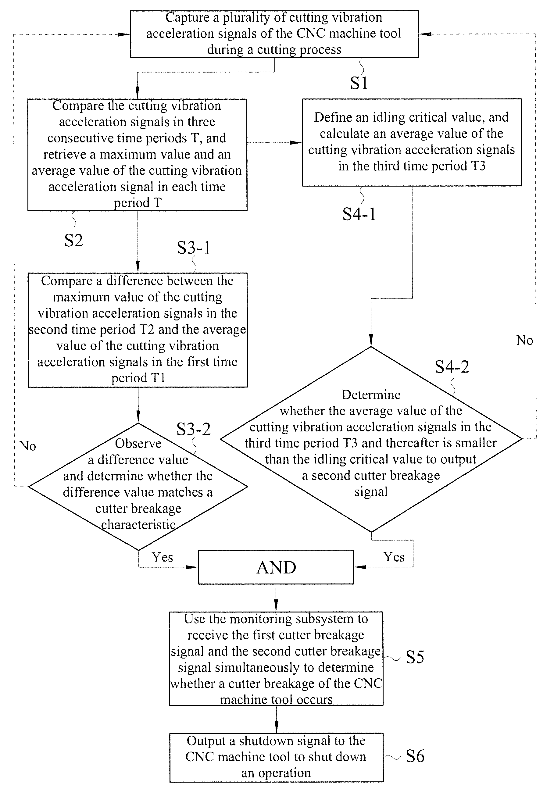
[0019]The technical contents of the present invention will become apparent with the detailed description of preferred embodiments and the illustration of related drawings as follows.

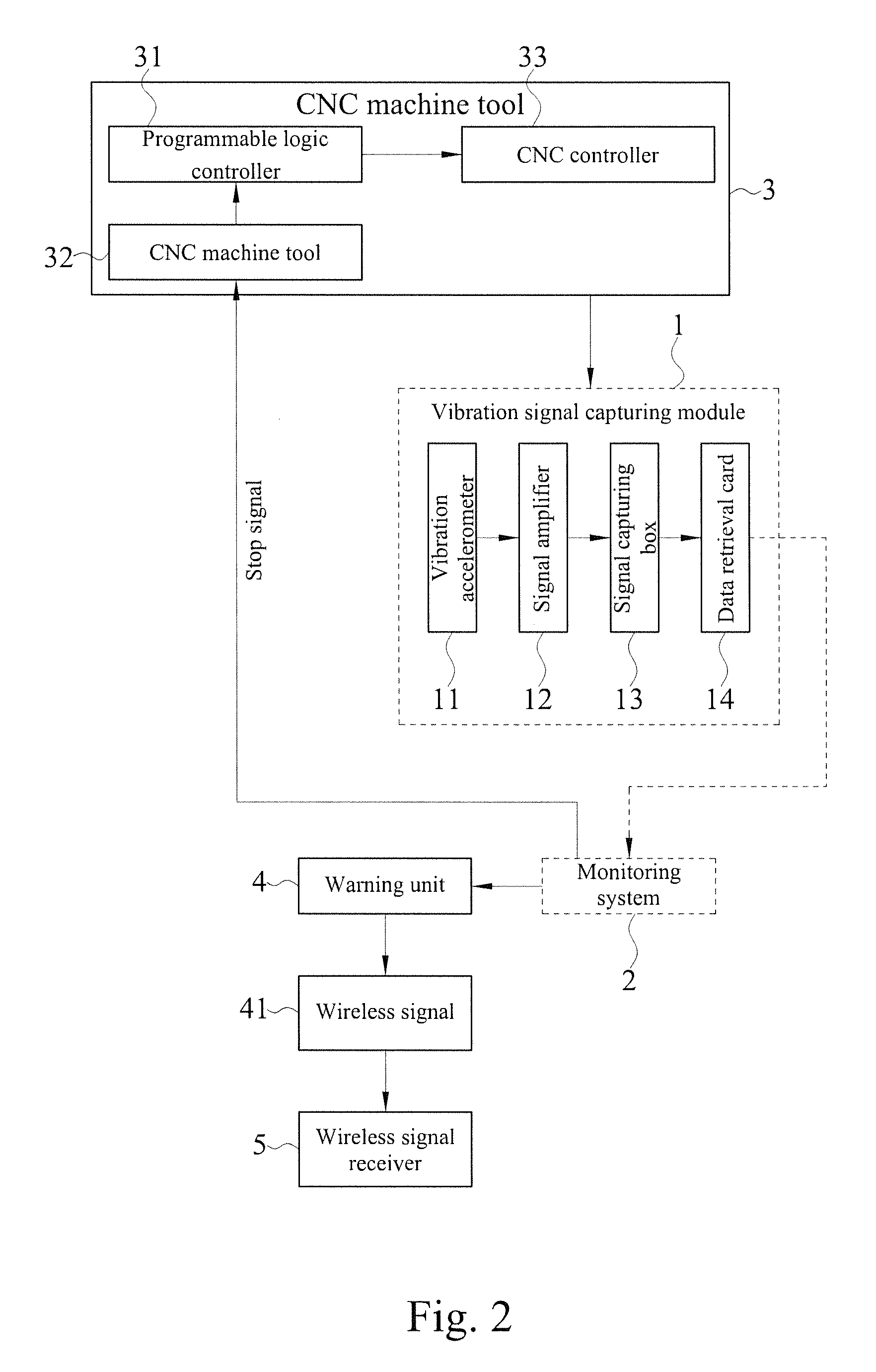
[0020]With reference to FIGS. 1 and 2 or a flow chart and a hardware block diagram of a cutter breakage monitoring method in accordance with a preferred embodiment of the present invention respectively, the online real-time cutter breakage monitoring method uses a vibration signal capturing module 1 and a monitoring subsystem 2 to monitor the cutting condition of a CNC machine tool 3, wherein the vibration signal capturing module 1 comprises a vibration accelerometer 11, a signal amplifier 12, a signal capturing box 13 and a data retrieval card (DAQ) 14, and the vibration accelerometer 11 is installed to a fixture (not shown in the figure) of the CNC machine tool 3 and electrically coupled to the signal amplifier 12, and the signal amplifier 12 is electrically coupled to the signal capturing box 13, and ...


PUM

PropertyMeasurementUnit
time periodaaaaaaaaaa
surface precisionaaaaaaaaaa
surface qualityaaaaaaaaaa

Abstract

An online real-time cutter breakage monitoring method uses a plurality of signals generated in three consecutive time periods by a vibration acceleration during a cutting process conducted by a CNC machine tool, and compares a difference between a maximum value of signals in each time period and an average value of the signals and a difference between the average value of signals thereafter and an idling critical value to output a first cutter breakage signal and a second cutter breakage signal simultaneously and determine the occurrence of a cutter breakage and shut down the CNC machine tool immediately to improve the determination speed and accuracy, so as to avoid unnecessary shutdowns or hindering the manufacturing flow.

Description

CROSS-REFERENCE TO RELATED APPLICATIONS[0001]This non-provisional application claims priority under 35 U.S.C. §119(a) on Patent Application No(s). 101104340 filed in Taiwan, R.O.C. on Feb. 10, 2012, the entire contents of which are hereby incorporated by reference.BACKGROUND OF THE INVENTION[0002]1. Field of the Invention[0003]The present invention relates to a cutting machine tool monitoring method, in particular to an online real-time cutter breakage monitoring method that uses a vibration acceleration signal to monitor a cutter breakage quickly during a cutting process.[0004]2. Description of the Related Art[0005]Cutting is a common manufacturing procedure applied in product manufacturing for removing extra materials on a workpiece to achieve a specific geometric shape and an appropriate surface precision, so that the cutting process must be stable. High speed machining (HSM) technology with the advantages of a high production efficiency, high manufacturing precision, and high su...

Claims


Application Information

Patent Timeline
Patent Type & Authority Patents(United States)
IPC IPC(8): G06F19/00B23Q17/09G05B19/4065
CPCG05B19/4065B23Q17/0971G05B2219/37233G05B2219/37435G05B2219/50205Y10T29/5153
Inventor WANG, SHIH-MINGHO, CHIEN-DA
Owner CHUNG YUAN CHRISTIAN UNIVERSITY
Why Eureka
Try Eureka