Pin lifting system

a lifting system and pin technology, applied in the field of wafer processing system, can solve the problems of inefficient or even at all, and inefficient or improper operation of esc b>106/b>, so as to reduce the lateral displacement of the pin

Active Publication Date: 2015-04-21
LAM RES CORP
View PDF10 Cites 6 Cited by
  • Summary
  • Abstract
  • Description
  • Claims
  • Application Information

AI Technical Summary

Benefits of technology

[0026]It is an object of the present invention to provide a pin lifting system that decreases the lateral displacement of the pin.

Problems solved by technology

ESC 106, in particular is a very expensive portion of wafer processing system 100.
As such, ESC 106 may not function efficiently, or even at all, if its physical integrity is degraded.
Such scraping may damage ESC 106, which may change the physical integrity of ESC 106, which may change operational parameters of ESC 106, and which may result in ESC 106 functioning inefficiently or improperly.
In such an event, ESC 106 must be repaired or replaced, either of which is costly.

Method used


Image

  • Pin lifting system
  • Pin lifting system
  • Pin lifting system

Examples


Embodiment Construction

[0047]An example embodiment of a pin lifting system in accordance with an aspect of the present invention will now be described with reference to FIGS. 11 and 12.

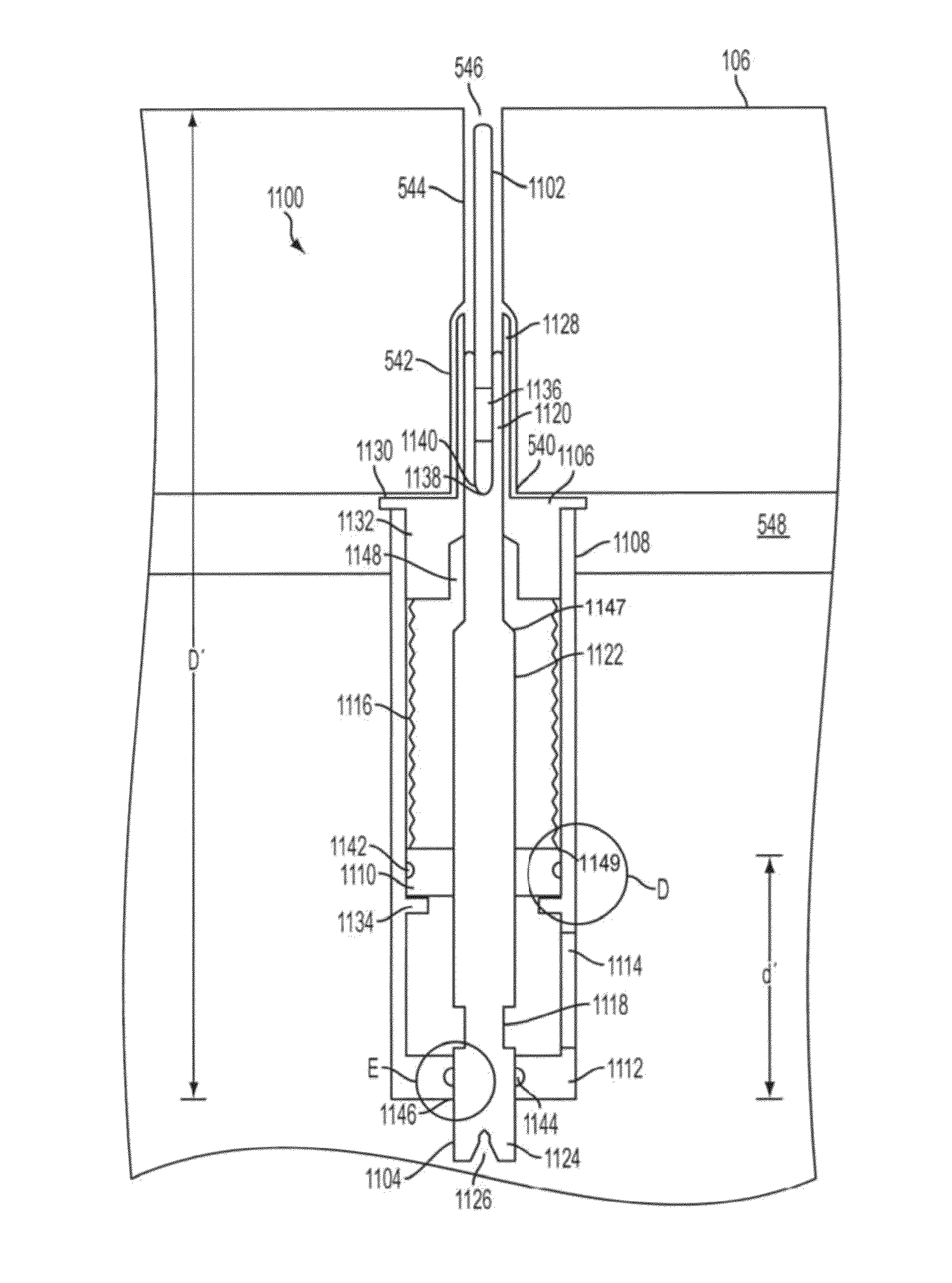
[0048]FIG. 11 illustrates an example pin lifting system 1100, in a first state, in accordance with an aspect of the present invention. As seen in the figure, pin lifting system 1100 includes a pin 1102, a pin retaining spring 1136, a pin holding shaft 1104, a housing neck 1106, a housing outer portion 1108 that includes a second bearing portion 1112, a first bearing 1110 and a bellows portion 1116. Housing outer portion 1108 has a window 1114 cut therein. Window 1114 enables a lifting arm (not shown) to lift pin holding shaft 1104 via a notch 1118. Pin holding shaft 1104 includes a pin holding portion 1120; an intermediate portion 1122 that includes a tapered portion 1147, and an end portion 1124, which includes an indentation 1126 and notch 1118. Housing neck 1106 includes a shaft guiding portion 1128, a cap portion 1130 a...


PUM

PropertyMeasurementUnit
distanceaaaaaaaaaa
distanceaaaaaaaaaa
distanceaaaaaaaaaa

Abstract

An aspect of the present invention is drawn to a device for use with an electrostatic chuck having a top surface and a bottom surface, the top surface being separated from the bottom surface by a width, the electrostatic chuck additionally having a hole therein, the hole having a first width at the top surface and having a second width at the bottom surface, the first width being less than the second width, the top surface being capable of having wafer disposed thereon. The device includes a pin, a shaft, a neck portion and an outer housing portion. The pin has a pin width less than the first width. The shaft has a pin-holding portion, an end portion and a central portion disposed between the pin-holding portion and the end portion. The central portion has a first bearing portion. The outer housing portion has a first end and a second end and includes a second bearing portion. The shaft is disposed within the outer housing portion and is moveable relative to the outer housing portion. The neck portion is disposed at the first end. The second bearing portion is stationary relative to the neck portion. The first bearing portion is movable relative to the second bearing portion.

Description

BACKGROUND[0001]Semiconductor wafers are processed in wafer processing systems. An example conventional wafer processing system will now be described with reference to FIGS. 1 and 2.[0002]FIGS. 1 and 2 illustrate a conventional wafer processing system. In the figures, wafer processing system 100 includes a confinement chamber portion 102, an electrode 104, an electrostatic chuck (ESC) 106, an electrode driving source 112, an ESC driving source 114 and a pin lifting system 116. Confinement chamber portion 102 has an input portion 108 and an output portion 110. Pin lifting system 116 includes a lifting pin 118. Confinement chamber portion 102 surrounds a processing space 122 used to process a semiconductor wafer 120.[0003]In operation, as illustrated in FIG. 1, semiconductor wafer 120 is disposed onto ESC 106. ESC driving source 114 applies a voltage to ESC 106, thereby creating an electric field, which creates a Coulomb force that holds semiconductor wafer 120 onto ESC 106. While sem...

Claims


Application Information

Patent Timeline
Patent Type & Authority Patents(United States)
IPC IPC(8): H01L21/67C23C16/458H01L21/683H01L21/687
CPCH01L21/6831H01L21/687H01L21/68742C23C16/4583C23C16/458H01L21/67Y10T279/34Y10T279/23
Inventor HAO, FANGLI J.
Owner LAM RES CORP
Why Eureka
Try Eureka