Ladle with transfer conduit

a transfer conduit and ladle technology, applied in the direction of manufacturing converters, charge manipulation, furnaces, etc., can solve the problems of molten metal interfering more, safety hazards, use of most transfer pumps, etc., to reduce the amount of turbulence, reduce the possibility of dross formation and air bubbles or pockets

Active Publication Date: 2015-04-21
MOLTEN METAL EQUIP INNOVIATIONS LLC
View PDF527 Cites 64 Cited by
  • Summary
  • Abstract
  • Description
  • Claims
  • Application Information

AI Technical Summary

Benefits of technology

[0022]The present disclosure relates to a transportable vessel that does not have to be tilted or tipped to pour molten metal out of it. The vessel includes a transfer conduit as part of the vessel. When a pump is placed into the transfer conduit and operated, it pumps molten metal out of the transportable vessel and into another structure preferably without tilting or tipping the transportable vessel. This avoids the potential dangers of spilling hot molten metal that can occur with the prior art method, generally more accurately fills ingot molds or other structures, and can reduce the amount of turbulence and thereby reduces potential dross formation and air bubbles or pockets.

Problems solved by technology

There are problems with each of these known methods.
This turbulence causes the molten metal to interact more with the air than would a smooth flow of molten metal pouring into the ladle.
The interaction with the air leads to the formation of dross within the ladle and splashing also creates a safety hazard because persons working near the ladle could be hit with molten metal.
Further, there are problems inherent with the use of most transfer pumps.
The blockage blocks the flow of molten metal through the pump and essentially causes a failure of the system.
This causes hours of expensive downtime.
The molten metal in the piping can also solidify causing failure of the system and downtime associated with replacing the piping.
Use of a tap-out hole at the bottom of a furnace can lead to problems.
First, when the tap-out plug is removed molten metal can splash or splatter causing a safety problem.
This is particularly true if the level of molten metal in the furnace is relatively high which leads to a relatively high pressure pushing molten metal out of the tap-out hole.
There is also a safety problem when the tap-out plug is reinserted into the tap-out hole because molten metal can splatter or splash onto personnel during this process.
Further, after the tap-out hole is plugged, it can still leak.
The leak may ultimately cause a fire, lead to physical harm of a person and / or the loss of a large amount of molten metal from the furnace that must then be cleaned up, or the leak and subsequent solidifying of the molten metal may lead to loss of the entire furnace.
Another problem with tap-out holes is that the molten metal at the bottom of the furnace can harden if not properly circulated thereby blocking the tap-out hole or the tap-out hole can be blocked by a piece of dross in the molten metal.
This system suffers from the problems previously described when using transfer pumps.
This is a dangerous and relatively difficult procedure because molten metal can spill or exit the transportable vessel unevenly, and turbulence may cause oxidation and dross to form.

Method used


Image

  • Ladle with transfer conduit
  • Ladle with transfer conduit
  • Ladle with transfer conduit

Examples


Embodiment Construction

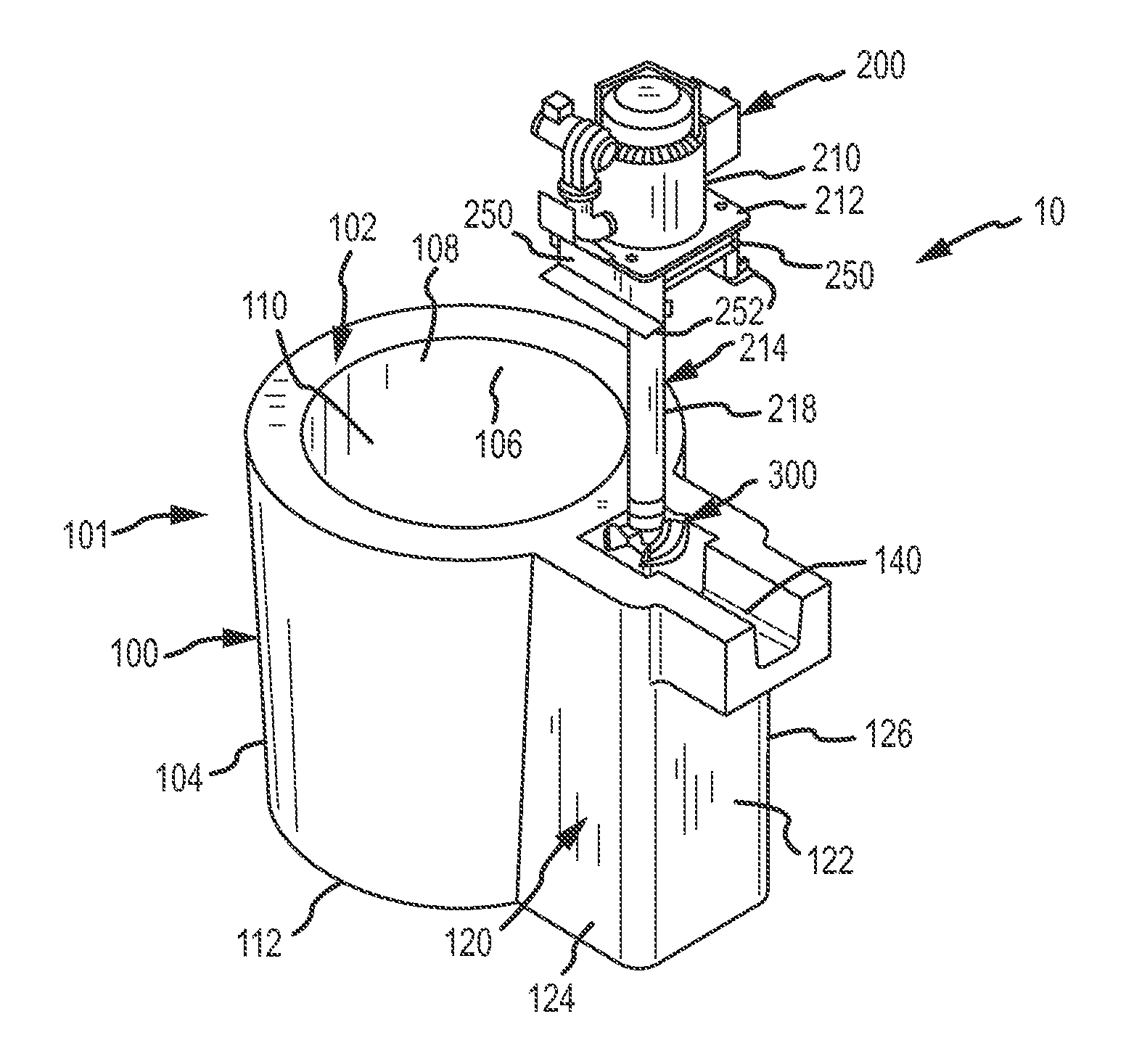
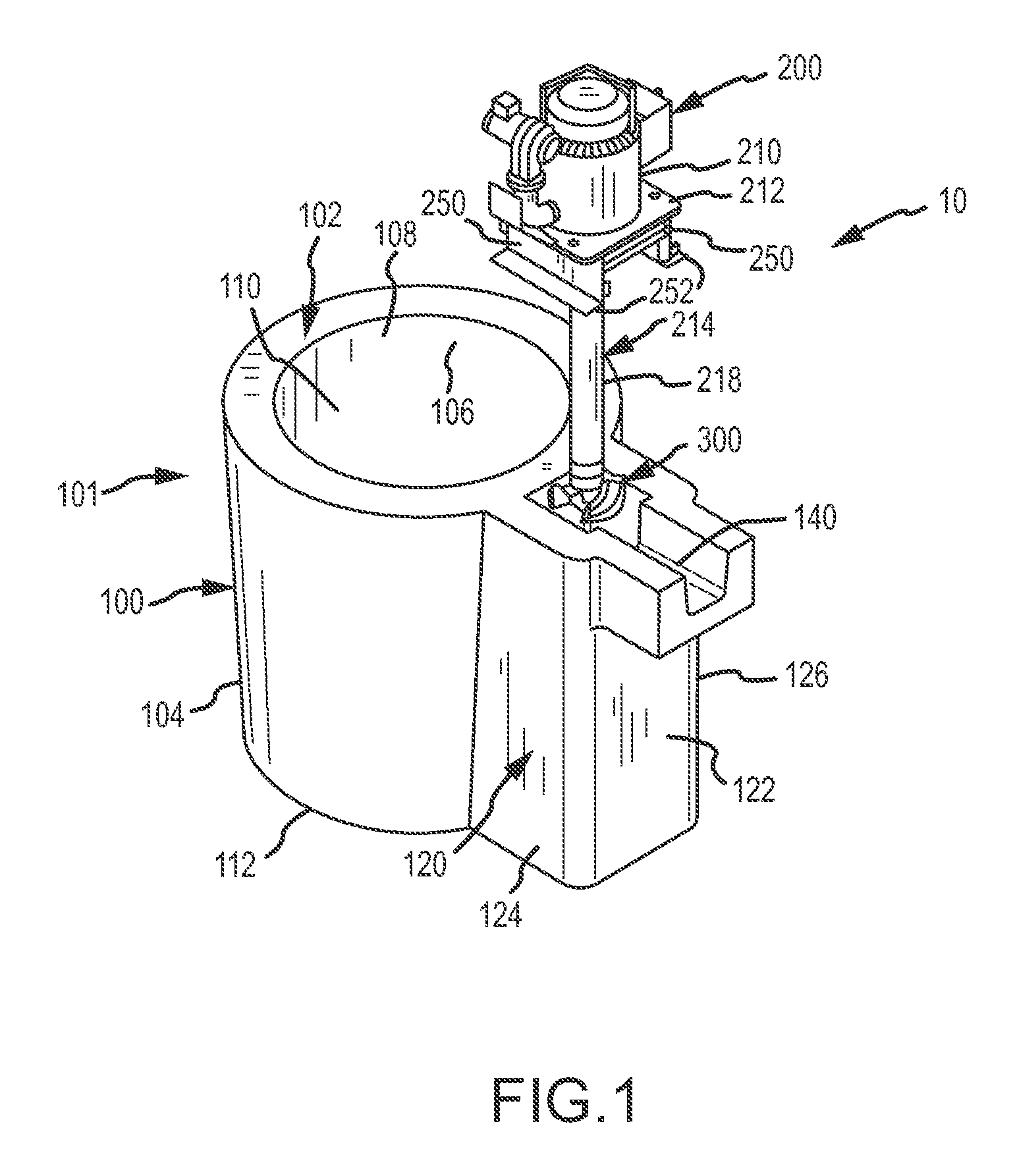
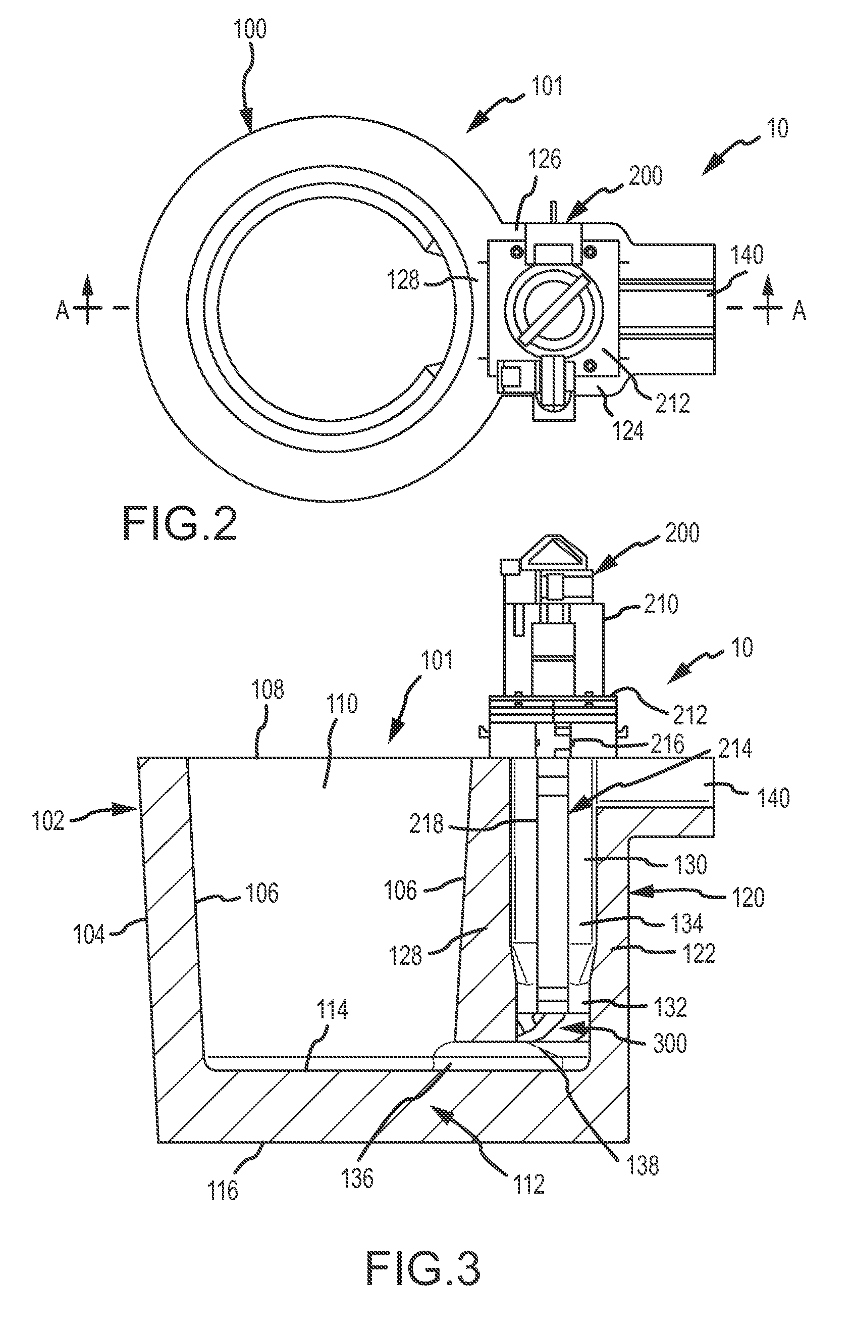
[0026]Turning now to the Figures, where the purpose is to describe preferred embodiments of the invention and not to limit same, FIGS. 1-3 show one preferred embodiment according to an aspect of the invention. A transportable vessel assembly 10 includes a transportable vessel 100 and a pump 200.

[0027]Vessel 100 is preferably made of any suitable refractory material wherein such materials are known to those skilled in the art. Vessel 100 has a holding portion 101 with a wall 102 that includes an outer surface 104 and an inner surface 106. As shown, wall 102 is cylindrical although it could be of any suitable shape. Holding portion 101 also has an opening 108 at its top that leads to an inner cavity 110, which retains molten metal placed therein. A bottom 112 is solid and has an inner surface 114 and an outer surface 116.

[0028]Vessel 100 also includes a transfer chamber 120, which is preferably comprised of the same material as holding portion 101. The material may be a high temperatu...


PUM

PropertyMeasurementUnit
horizontal angleaaaaaaaaaa

Abstract

Disclosed is a transportable vessel for use in a factory for processing molten metal. The vessel is not connected to a reverbatory furnace and can be moved to different locations in the factory. The vessel includes a transfer conduit in communication with a cavity of the vessel. A molten metal pump can be positioned in the transfer conduit to move molten metal out of an outlet in communication with the transfer conduit and into another vessel without the need to tip or tilt the transportable vessel.

Description

FIELD OF THE INVENTION[0001]The present invention relates to a portable vessel, particularly a ladle, used in molten metal processing. The portable vessel (hereafter sometimes referred to as “vessel”) does not include a heating element and is not part of a reverbatory furnace. A molten metal pump may be included as part of a system utilizing the vessel. This application incorporates by reference the portions of U.S. patent application Ser. No. 13 / 797,616, filed on Mar. 12, 2013, by Paul V. Cooper and U.S. patent application Ser. No. 13 / 802,040, filed on Mar. 13, 2013, by Paul V. Cooper that are not inconsistent with this disclosure.BACKGROUND OF THE INVENTION[0002]As used herein, the term “molten metal” means any metal or combination of metals in liquid form, such as aluminum, copper, iron, zinc and alloys thereof. The term “gas” means any gas or combination of gases, including argon, nitrogen, chlorine, fluorine, Freon, and helium, which may be released into molten metal.[0003]A re...

Claims


Application Information

Patent Timeline
Patent Type & Authority Patents(United States)
IPC IPC(8): B22D41/12B22D39/00B22D41/00
CPCB22D41/12B22D39/00B22D41/00F27D3/12F27D27/005
Inventor COOPER, PAUL V.
Owner MOLTEN METAL EQUIP INNOVIATIONS LLC
Why Eureka
Try Eureka