Soft turn-on in an ignition system of a combustion engine

a technology of ignition system and combustion engine, which is applied in the field of electrics, can solve the problems of serious engine damage, lowering efficiency, and unsatisfactory ignition spark

a technology of ignition system and combustion engine, which is applied in the field of electrics, can solve the problems of serious engine damage, lowering efficiency, and unsatisfactory ignition spark

US9013224B2Active Publication Date: 2015-04-21STMICROELECTRONICS SRL

Image

  • Soft turn-on in an ignition system of a combustion engine
  • Soft turn-on in an ignition system of a combustion engine
  • Soft turn-on in an ignition system of a combustion engine

Examples


Embodiment Construction

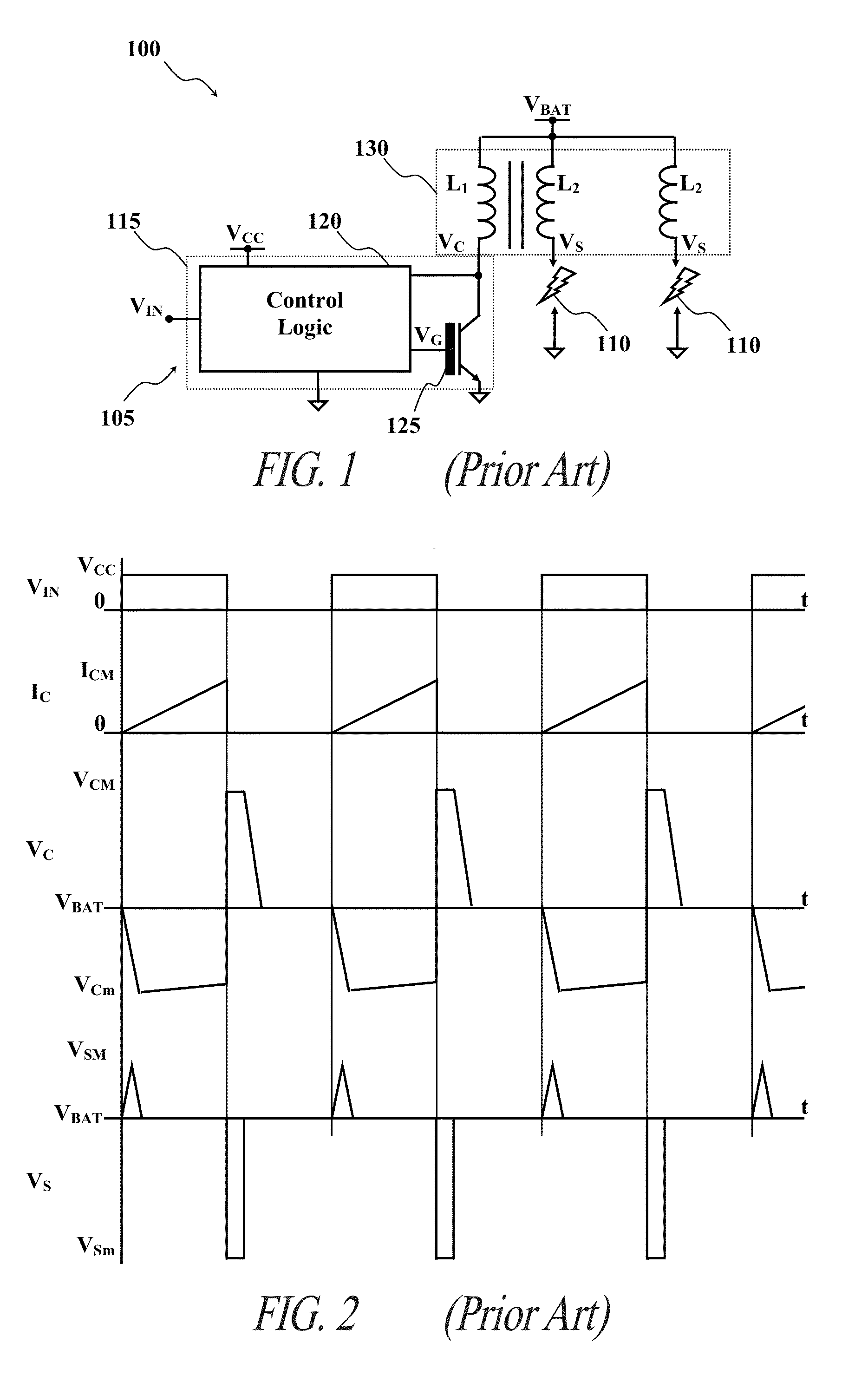
[0035]With reference in particular to the FIG. 1, a portion of a known combustion engine 100 (for example, for automotive applications) is shown. The combustion engine 100 comprises an electronic ignition system 105, which is used to control the firing of ignition sparks in one or more spark plugs 110 (two in the drawing) of the combustion engine 100.

[0036]The ignition system 105 is based on a switching system 115, which comprises a control logic circuit 120 and a switching device, such as an IGBT 125, controlled by the control logic 120. In detail, the control logic 120 is supplied by a reference (or ground) voltage and a supply voltage VCC (typically, 5V with respect to the ground voltage. In another embodiment, the control logic 120 is directly supplied with battery voltage (6-18V) and includes an internal voltage regulator (not shown) configured to generate Vcc=5. The control logic 120 receives a switching command VIN, which in the example is a logical signal that may be asserte...


PUM


Abstract

A switching system for a combustion engine ignition system comprises a switching device switchable between an accumulation condition and a transfer condition to activate an ignition element. The switching system comprises control logic that provides a control signal for controlling the switching device, measures a progress indicator indicative of progress in switching the switching device from the transfer condition to the accumulation condition, and causes the control signal to vary with a first variation rate during a first stage until the progress indicator reaches a first progress condition. The control logic causes the control signal to vary with a second variation rate, lower than the first variation rate, during a second stage until the progress indicator reaches a second progress condition, and causes the control signal to vary with a third variation rate, higher than the second variation rate, during a third stage of the preliminary switching.

Description

BACKGROUND[0001]1. Technical field[0002]The solution according to one or more embodiments of the present disclosure generally relates to the field of electronics. More particularly, this solution relates to switching systems for igniting combustion engines.[0003]2. Description of the Related Art[0004]Nowadays, in almost every combustion engine (for example, in the automotive field) the ignition of a corresponding combustion is usually provoked by an ignition system of the electronic type. Typically, the ignition system comprises a switching device (for example, an insulated gate bipolar transistor, or IGBT), which controls the ignition sparks of spark plugs of the combustion engine. For this purpose, the IGBT is coupled with a primary winding of a transformer; the transformer has one or more secondary windings, each of which is coupled with a respective spark plug. During each cycle of the combustion engine, the IGBT is firstly turned on by applying a suitable voltage to its gate te...

Claims


Application Information

Patent Timeline
21 Apr 2015
Publication
US9013224B2
IPC
H03K17/04; F02P3/04; F02P3/05; F02P11/02; H03K17/16
CPC
F02P3/0435; F02P3/05; F02P11/02; H03K17/168; H03K17/166
Inventors
TRECARICHI, CALOGERO ANDREA; TORRISI, GIOVANNI LUCA