CT collimator and CT system including the CT collimator

a collimator and collimator technology, applied in the field of radiograph ct, can solve the problems of higher cos

Active Publication Date: 2015-04-21
GE MEDICAL SYST GLOBAL TECH CO LLC
View PDF1 Cites 18 Cited by
  • Summary
  • Abstract
  • Description
  • Claims
  • Application Information

AI Technical Summary

Benefits of technology

[0017]According to an embodiment of the present invention, there is provided a CT system. The CT system comprises a CT collimator according to the first aspect of the present invention, a radiation detection area monitoring unit disposed on a radiation detector, and a collimator controller that selects one of a plurality of blades of the rotating slot part according to a region of interest of a subject to allow a desired radiation beam to be projected to the region of interest of the subject, wherein the radiation detection area monitoring unit monitors, during a CT scan, an offset of the radiation detection area on the radiation detector caused by focus shift of the radiation source as radiation beam is projected to the radiation detector via the selected blade of the CT collimator, and wherein the collimator controller is configured to correct an angle of rotation of the rotating slot part of the CT collimator according to the monitored offset received from the radiation detection area monitoring unit to eliminate the offset of the radiation detection area caused by the focus shift of the radiation source for performing Z-beam tracking.
[0027]In the CT collimator and CT system comprising said CT collimator according to embodiments of the present invention, a plurality of blades having variable slot widths can be provided in the CT collimator according to the needs of a CT scan. An edge of each blade slot along a longitudinal direction of the blade has a convex curved surface structure (namely, in a vertical plane along a longitudinal direction of the blade slot, the two side edges of the slot are curved) so that when a focus shift of the radiation source along a focus shift path occurs as a result of temperature change, by rotating the selected blade about the rotation center eccentric to the blade a correction angle corresponding to the focus shift, the radiation beams reaching the radiation detector via the blade slot are maintained at the same region as the circumstance where focus shift does not occur. Therefore, the CT collimator and CT system according to an embodiment of the present invention eliminate the need to relocate other components such as the radiation detector or the subject when a focus shift of the radiation source occurs.

Problems solved by technology

Such a collimator comprises at least two gates or cams, which are driven by at least two different motor drive systems, and hence have higher cost.

Method used


Image

  • CT collimator and CT system including the CT collimator
  • CT collimator and CT system including the CT collimator
  • CT collimator and CT system including the CT collimator

Examples


Embodiment Construction

[0035]In the following detailed description, exemplary embodiments of the present invention are described with reference to the accompanying drawings. However, it will be appreciated by persons skilled in the art that the present invention is not limited to these exemplary embodiments.

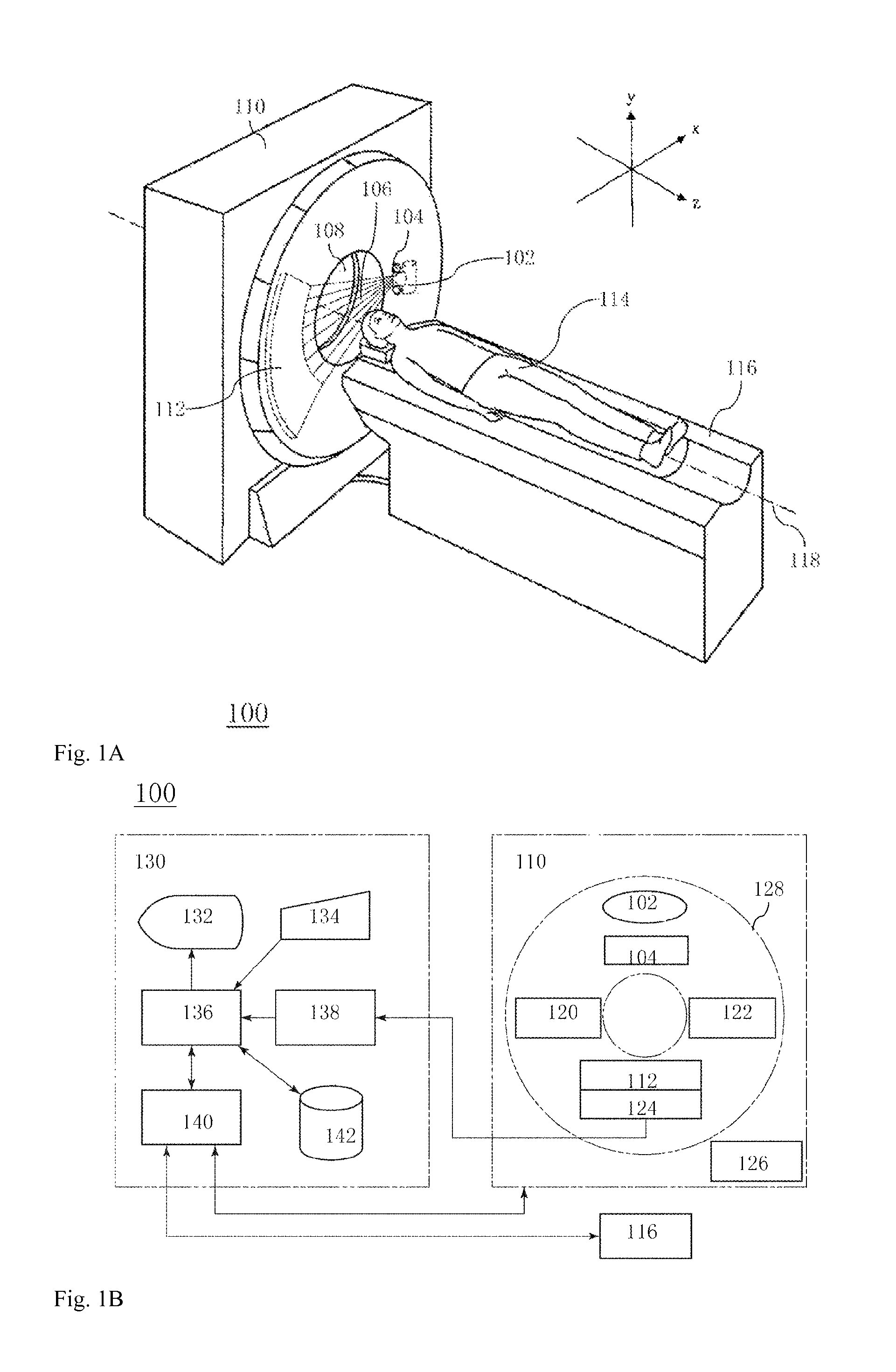
[0036]FIGS. 1A and 1B show a radiograph CT system 100 according to an exemplary embodiment of the present invention. In an embodiment, the radiograph CT system 100 is an X-ray CT system.

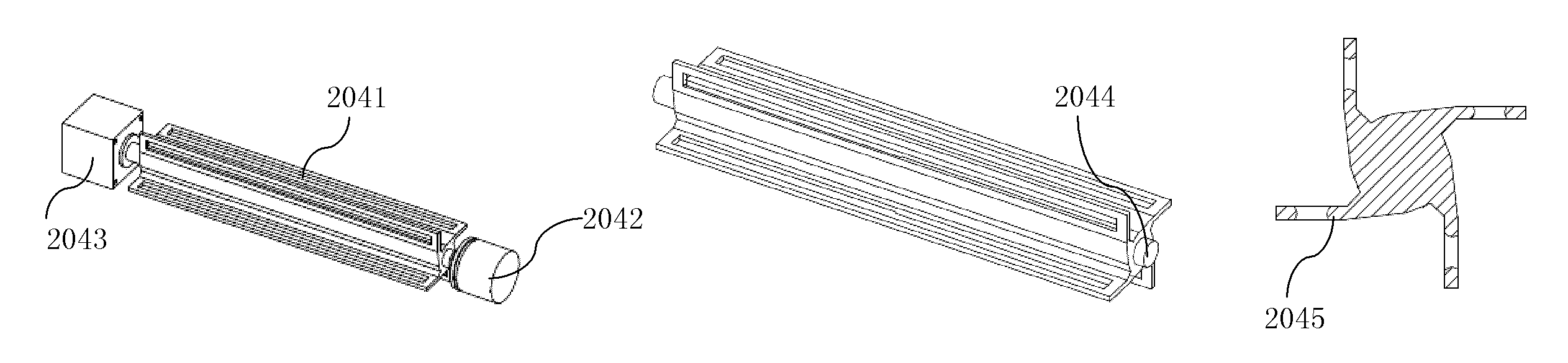
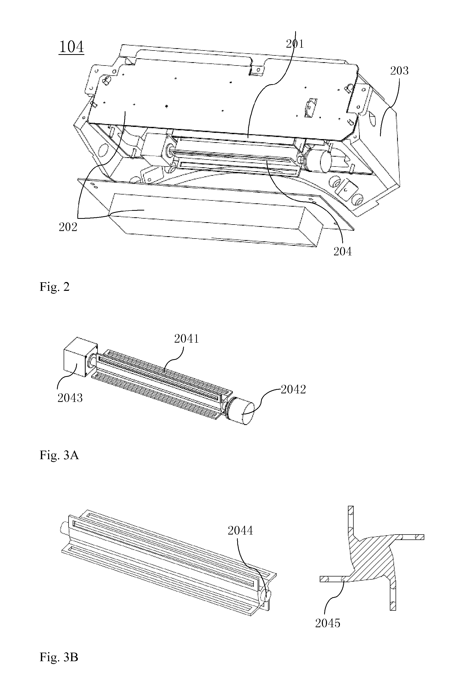
[0037]As shown in FIGS. 1A and 1B, the X-ray CT system 100 mainly includes three parts: a scan gantry 110, a support table 116 for positioning a subject 114 to be detected, and an operation console 130. The scan gantry 110 includes an X-ray tube 102. X-rays 106 emitted from the X-ray tube 102 pass through a collimator 104 to form an X-ray beam of such shapes as fan shaped beam and cone shaped beam, to be irradiated to a region of interest of the subject 114. The X-ray beam that passes through the subject 114 is applied ...


PUM


Abstract

A CT collimator comprising a rotating slot part on a rotation shaft and having a plurality of blades, each blade has a slot of a different width and a radiation beam entering the collimator can only pass via a slot in one of the blades, each edge of each blade slot along a longitudinal direction has a convex curved surface structure, and in a vertical plane along a longitudinal direction, two side edges of the slot are curved, and each blade is arranged to be eccentric to the center of the rotation shaft. A CT system using the CT collimator, the detection area of the radiation rays projected to the radiation detector via the CT collimator can be maintained unchanged by adjusting the rotation angle of the blade, under the circumstance where the focus of the radiation source shifts during a CT scan.

Description

BACKGROUND TO THE INVENTION[0001]The present application relates to the field of radiograph CT, and more particularly, to a CT collimator having a single motor drive system and a radiograph CT system having the CT collimator.[0002]At present, radiograph CT systems such as X-ray CT system are widely used in various medical institutions for three-dimensional imaging of the regions of interest of the subjects to assist the clinicians to achieve an accurate medical diagnosis of the subjects.[0003]In a radiograph CT system, a radiation tube generating cone-shaped radiation beams and a detector detecting the radiation beams rotate around a rotation center, wherein the detector is disposed opposite to the radiation tube and consists of detector elements arranged in a matrix form. Projection data generated by the radiation beams transmitting through the subject are collected; based on the collected projection data, an image of the region of interest of the subject is reconstructed; and then...

Claims


Application Information

Patent Timeline
Patent Type & Authority Patents(United States)
IPC IPC(8): G21K1/02A61B6/00A61B6/03A61B6/06
CPCG21K1/02A61B6/03A61B6/06A61B6/547A61B6/4021A61B6/467
Inventor ZHANG, XIAOYANGUO, JUNYANG, XUYONG
Owner GE MEDICAL SYST GLOBAL TECH CO LLC
Why Eureka
Try Eureka