Information processing apparatus and information processing method for processing image information at an arbitrary viewpoint in a physical space or virtual space

a technology of image information and information processing apparatus, which is applied in the field of information processing apparatus and information processing method for processing image information at an arbitrary viewpoint in a physical space or virtual space, can solve the problems of lack of depth cues, inability to maintain saturation and definition of the match between the virtual object and the real object, and difficulty in image pickup apparatus, e.g., a video camera, to achieve the effect of reducing perception

Inactive Publication Date: 2015-04-21
CANON KK
View PDF25 Cites 37 Cited by
  • Summary
  • Abstract
  • Description
  • Claims
  • Application Information

AI Technical Summary

Benefits of technology

[0026]An exemplary embodiment of the present invention provides an information processing apparatus and method for processing image information obtained from an arbitrary viewpoint in a real space or a virtual space, wherein a difference in perception can be avoided from occurring in the image information obtained from the arbitrary viewpoint between the real space and virtual space.

Problems solved by technology

However, matching between the virtual object and the real object cannot be maintained in saturation and definition.
The second cause is lack of depth cues.
Meanwhile, it is difficult for an image pickup apparatus, e.g., a video camera, to change the position and the direction of the apparatus based on information regarding visual actions of a photographer.
However, those constructions inevitably enlarge the system size and increase the cost.
Another problem is that, because of a longer processing time, those constructions cannot be applied to a system which requires real time processing.
Still another problem is as follows.
However, the matching in configuration (shape and size) is lost when the object is viewed from a different position and direction.

Method used


Image

  • Information processing apparatus and information processing method for processing image information at an arbitrary viewpoint in a physical space or virtual space
  • Information processing apparatus and information processing method for processing image information at an arbitrary viewpoint in a physical space or virtual space
  • Information processing apparatus and information processing method for processing image information at an arbitrary viewpoint in a physical space or virtual space

Examples


first exemplary embodiment

1. Configuration of MR System

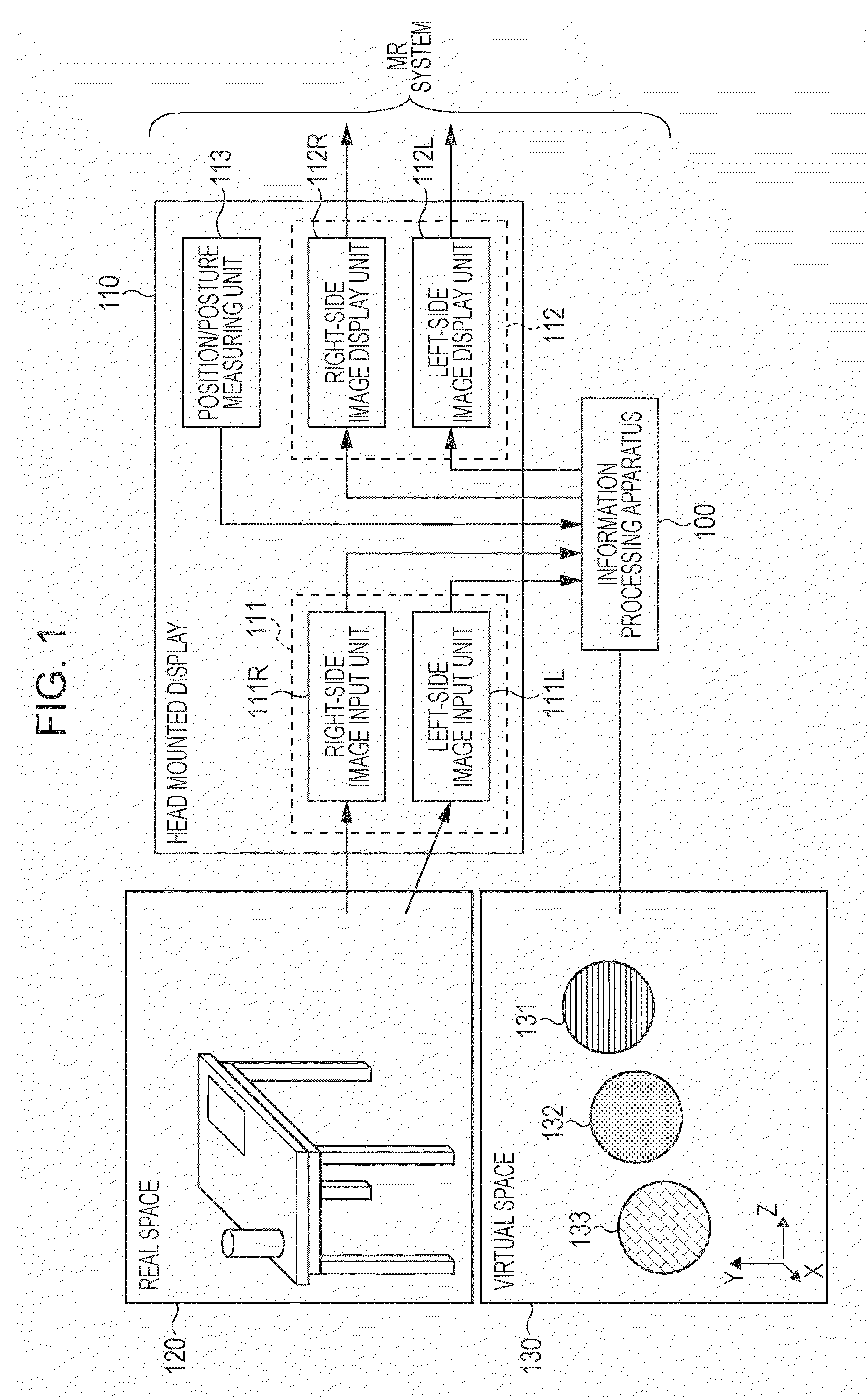
[0051]FIG. 1 illustrates an entire configuration of an MR system in combination of an information processing apparatus 100 according to a first exemplary embodiment of the present invention and an HMD 110.

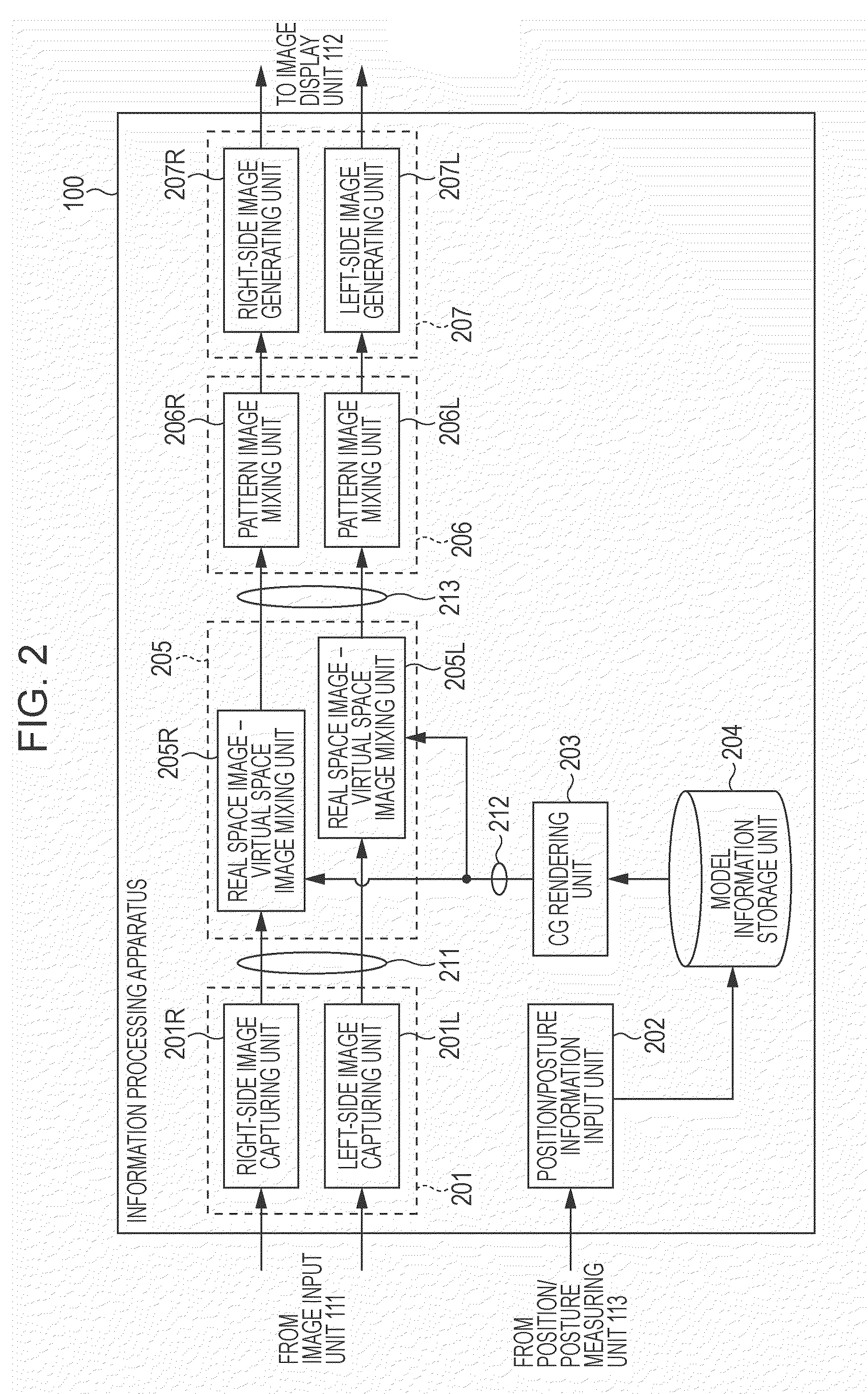
[0052]Referring to FIG. 1, the information processing apparatus 100 generates an MR image (displayed image) by mixing (combining) a real space image obtained by taking an image of a real space 120 and a virtual space image, which is obtained by looking at a virtual object in a virtual space 130 from a predetermined position and direction. Further, the information processing apparatus 100 generates an output image by superimposing, on the generated MR image, a predetermined pattern image which induces an illusion in user's perception. In addition, the information processing apparatus 100 executes control for displaying the generated output image on the HMD 110.

[0053]The HMD 110 includes an image input unit 111 for taking an image of the real space 120 an...

second exemplary embodiment

[0092]In the above-described first exemplary embodiment, the pattern image is separately superimposed on the segmented regions in each of the generated MR images (i.e., in the MR image corresponding to one frame) for the purpose of reducing the difference in depth perception.

[0093]However, the scope of the present invention is not limited to the first exemplary embodiment. For example, the pattern image can also be superimposed, taking into account motions (optical flow) of each object in the MR images covering a plurality of frames.

[0094]FIGS. 7A to 7D illustrate examples of the pattern image generated by the pattern image generating unit 403 in the information processing apparatus 100 according to a second exemplary embodiment of the present invention.

[0095]FIG. 7A illustrates the segmented image 411 at a time T1. Also, FIG. 7B illustrates the segmented image 411 at a time T2. Between the time T1 and the time T2, the virtual object images 301 to 303 in the segmented image 411 appe...

third exemplary embodiment

[0110]The first and second exemplary embodiments have been described as selectively segmenting the virtual space image from the MR image by the MR image region segmentation unit 402. However, the scope of the present invention is not limited to the described segmentation method.

[0111]For example, a distance sensor may be disposed on the HMD 110 to segment, based on distance information output from the distance sensor, a region defined by each of objects within the real space image, which is positioned at a predetermined distance.

[0112]FIG. 8 is a block diagram illustrating a functional configuration of a pattern image mixing unit when a region is segmented based on distance information. Note that components having the same functions as those of the pattern image mixing units 206R and 206L, illustrated in FIG. 4, are denoted by the same reference numerals.

[0113]Referring to FIG. 8, a feature detecting unit 801 obtains distance information (feature information) sent from the HMD 110. ...


PUM


Abstract

An information processing apparatus configured to generate an MR image displayed on a display apparatus includes a segmentation unit configured to segment the generated MR image into a plurality of regions, a generation unit configured to generate a pattern image to be superimposed on one of the plurality of segmented regions or each of the plurality of segmented regions, a superimposition unit configured to superimpose the generated pattern image on one of the plurality of segmented regions or each of the plurality of segmented regions, and an output unit configured to output the MR image, including the pattern image superimposed thereon, to the display apparatus.

Description

BACKGROUND OF THE INVENTION[0001]1. Field of the Invention[0002]The present invention relates to an information processing techniques useful in an information processing apparatus configured to process image information at an arbitrary viewpoint in a real (physical) space or a virtual space.[0003]2. Description of the Related Art[0004]Hitherto, it is known that controlling a stimulus given to the human sense of sight, for example, can cause a person to have perception in a state differing from the inherent state.[0005]With the techniques represented by computer graphics (hereinafter abbreviated to “CG”), etc., a virtual object drawn on a two-dimensional plane is displayed as if it exists three-dimensionally, in consideration of human spatial perception characteristics. In the case of CG, perception (e.g., perception representing a three-dimensional object) differing from that corresponding to the inherent state (e.g., a two-dimensionally expressed object) is generated by controlling...

Claims


Application Information

Patent Timeline
Patent Type & Authority Patents(United States)
IPC IPC(8): G06K9/00G06T19/00
CPCG06T19/00G06T19/006
Inventor KATANO, YASUOSUZUKI, MASAHIRO
Owner CANON KK
Why Eureka
Try Eureka