Turbine engine blade

a turbine engine and blade technology, applied in the direction of liquid fuel engines, marine propulsion, vessel construction, etc., can solve the problems of secondary phenomena, reduced propulsive efficiency, and additional mechanical fatigue, so as to reduce mechanical fatigue and reduce the load on the blade

Active Publication Date: 2015-05-05
SN DETUDE & DE CONSTR DE MOTEURS DAVIATION S N E C M A
View PDF9 Cites 5 Cited by
  • Summary
  • Abstract
  • Description
  • Claims
  • Application Information

AI Technical Summary

Benefits of technology

[0011]Thus, a main object of the present invention is to limit the secondary phenomena that are generated on the suction side of a turbine engine blade, in particular a rotor wheel blade of the first or second stage of a turbojet, by optimizing the shape of the blade.
[0015]While conserving a mean deviation value that is comparable to the values of existing blades, the applicant has found that this specific shape serves to reduce the load on blades in the regions of their roots and of their tips.
[0016]As a result, the above-mentioned secondary vortex phenomena are decreased, in particular those that occur in the regions of the wall, of the root, and of the tip. Since loads are clearly reduced in those regions, the blade is also subjected to less mechanical fatigue than in the prior art.
[0018]This makes it possible to reduce very clearly the load on the blade at its roots, a region in which wall phenomena are the most significant, while obtaining the desired mean deviation, with deviation being a little greater at the tip than at the root.
[0028]Whereas, on the other hand, the deviation maximum lies in the range 60% to 90% of the height H of the blade, this clear reduction makes it possible to bring the deviation at the tip of the blade to a small value, a value that is only slightly greater than the deviation observed at the root of the blade.

Problems solved by technology

Furthermore, they give rise locally to pressure gradients that can reduce propulsive efficiency and constitute an additional source of mechanical fatigue.
Those solutions present a certain amount of effectiveness, but when they are employed, secondary phenomena continue to exist, even if they are reduced.

Method used


Image

  • Turbine engine blade
  • Turbine engine blade
  • Turbine engine blade

Examples


Embodiment Construction

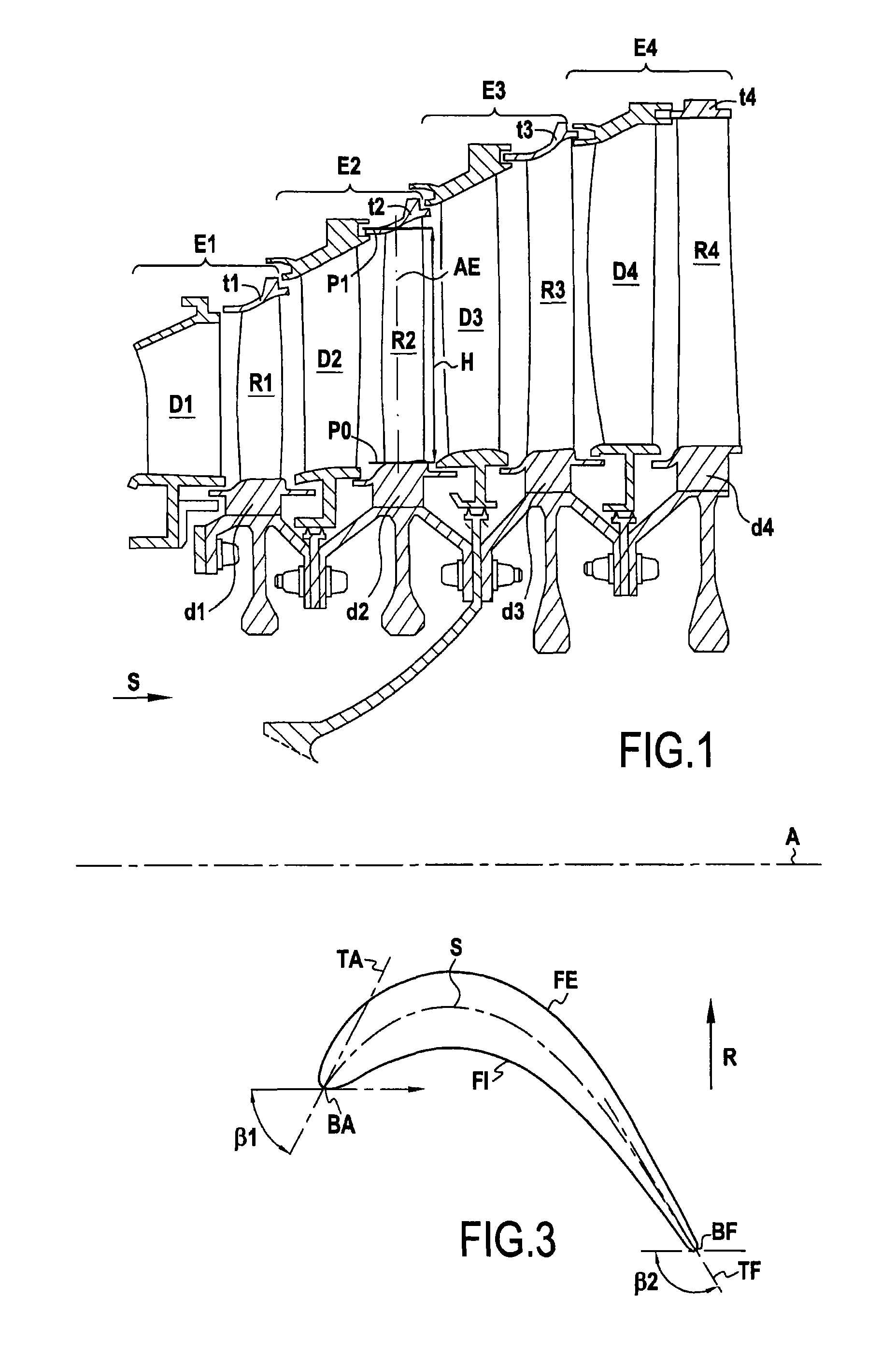
[0037]The turbine shown in axial section in FIG. 1 has four stages referenced respectively E1 to E4. In the direction S going from upstream to downstream, each stage comprises a nozzle forming a stator portion of the turbine and having a plurality of radially-oriented vanes, and a rotor wheel forming a rotor portion of the turbine and comprising a plurality of radially-oriented blades.

[0038]In FIG. 1, the nozzle vanes of stages E1 to E4 are respectively referenced D1 to D4, and the blades of the rotor wheels of stages E1 to E4 are respectively referenced R1 to R4.

[0039]The nozzle vanes are fastened at both ends to stationary structure portions, while the blades of the rotor wheels are fastened to rotary disks, respectively referenced d1 to d4 via their roots, which are formed at their radially inner ends, closer to the axis of rotation A of the turbine. In the example shown, the tips of the rotor wheel blades, formed at their radially outer ends, carry outer platforms respectively r...


PUM


Abstract

A turbine engine blade having a plurality of blade sections stacked along a radial axis between a root and a tip. Each section extends along a longitudinal axis between a leading edge and a trailing edge, and along a tangential axis between a pressure-side face and a suction-side face. Each section presents a camber line, a deviation defined for each section as the difference between an angle between the tangent to the camber line at the leading edge and the longitudinal axis, and an angle between the tangent to the camber line at the trailing edge and the longitudinal axis. The minimum deviation is at the root of the blade, and the maximum deviation is present at sections situated in the range 0.3H to 0.8H, where H is the height of the blade measured from its root to its tip.

Description

BACKGROUND OF THE INVENTION[0001]The present invention relates to a turbine engine blade, and more particularly to a blade of a rotor wheel of a turbine engine.[0002]The invention relates more particularly to a rotor wheel of a low-pressure gas turbine of the type used in an aviation turbojet.[0003]Conventionally, a turbojet has a plurality of nozzle stages, e.g. four stages. Each stage comprises a stationary nozzle forming a stator, and a rotor wheel, the nozzle and the wheel each having a plurality of vanes or blades organized radially relative to the longitudinal axis of the turbojet, which is the axis of rotation of the wheel.[0004]Below, it is assumed that the axial direction X is the direction of the axis of rotation of the wheel on which the blade is to be mounted, that the radial direction Z is the height direction of the blade between its root and its tip, and that the tangential direction Y is the direction perpendicular to the axial and radial directions.[0005]The inventi...

Claims


Application Information

Patent Timeline
Patent Type & Authority Patents(United States)
IPC IPC(8): F01D5/14
CPCF01D5/141F01D5/148F01D5/145F05D2220/3213F05D2240/301F05D2250/71F05D2250/314Y02T50/673Y02T50/60
Inventor ROYAN, RENAUD GABRIEL CONSTANTMARTET, RENAUDGUIMBARD, JEAN-MICHEL
Owner SN DETUDE & DE CONSTR DE MOTEURS DAVIATION S N E C M A
Why Eureka
Try Eureka