Device for inductive transmission of electrical energy

a technology of inductive transmission and electrical energy, applied in the direction of transformer/inductance circuit, electric vehicle, inductance, etc., can solve the problems of limiting the acceptance of inductive energy transmission in many population circles, damage and/or hazards, and hazard assessment as not relevant, so as to improve the operating safety of inductive energy transmission system

Active Publication Date: 2015-05-05
IPT TECH
View PDF49 Cites 8 Cited by
  • Summary
  • Abstract
  • Description
  • Claims
  • Application Information

AI Technical Summary

Benefits of technology

[0006]Therefore, the underlying object of the invention is to improve the operating safety of an inductive energy transmission system with regard to the presence of foreign bodies in the area of the field.
[0008]According to the invention, with a device for inductive transmission of electrical energy from a stationary unit with at least one primary inductor to a vehicle standing in the vicinity hereof and having at least one secondary inductor, the stationary unit or the vehicle has a device for detecting the presence of an object inside a predetermined space which at least comprises the space lying between the primary inductor and the secondary inductor during the transmission of energy. This makes it possible to detect the introduction of a foreign body into the area of the field produced by the energy transmission and to react in a suitable manner.

Problems solved by technology

Although it can be assumed that this usually does not lead to any direct hazard, particularly as there is no fear of protracted presence in this space, however the possibility of accidental exposure of children or domestic animals in particular to a strong magnetic field is likely to limit acceptance of inductive energy transmission in many population circles.
In the presence of such conditions, temperatures can be reached which can lead to damage and / or hazards.
Due to the characteristics of existing applications for inductive energy transmission systems, such a hazard was assessed as not being relevant.
However, the presence of foreign bodies in the area of the field appears to be an obvious safety problem for largely automatic operation or with higher safety requirements which must be assumed when such systems are used in areas accessible to the public.
Furthermore, the vehicle will usually be completely unsupervised during the major part of a charging operation.

Method used


Image

  • Device for inductive transmission of electrical energy
  • Device for inductive transmission of electrical energy
  • Device for inductive transmission of electrical energy

Examples


Embodiment Construction

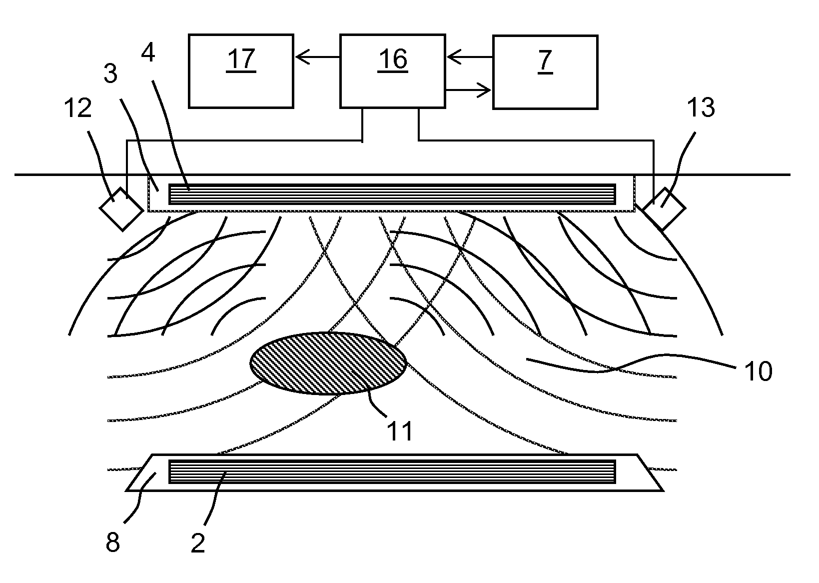
[0016]FIG. 1 shows a diagrammatic sectional view (at the top) and a diagrammatic plan view (at the bottom) of an electric vehicle 1 standing over the primary coil 2 of a charging station to charge its battery. On the underside of the vehicle 1 in a housing 3 there is a secondary coil 4 which is connected to an electronic charging unit 5. This converts the parameters of the electric power transmitted inductively to the secondary coil 4 into suitable values for charging the battery of the vehicle 1. The primary coil 2 is fed by a current supply unit 6 of the charging station and is located in a housing 8 which is positioned statically in a vehicle parking bay. The current supply unit 6 is controlled by a control unit 7 of the charging station.

[0017]Some of the field lines 9 of the alternating magnetic field produced by the primary coil 2 while in operation are indicated by the dashed lines in FIG. 1. The main direction of the field is the direction of the coil axis of the primary coil...


PUM

PropertyMeasurementUnit
electrical energyaaaaaaaaaa
timeaaaaaaaaaa
currentaaaaaaaaaa

Abstract

The invention relates to a device for the inductive transfer of electric energy from a stationary unit comprising at least one primary inductance to a vehicle that is adjacent to said unit and has at least one second inductance. The stationary unit or the vehicle has a device for detecting the presence of an object in a predetermined area that covers at least the area lying between the primary inductance and the second inductance during the inductive energy transfer. The detection device has at least one contactless sensor and an evaluation unit that is connected to the sensor. At least the sensor of the detection device is integrated into or mounted on the same housing as the primary or secondary coil of the energy transfer device. The sensor can be an ultrasonic sensor, radar sensor, infra-red sensor or an electric image sensor.

Description

FIELD OF THE INVENTION[0001]The invention relates to a device for inductive transmission of electrical energy according to the preamble of claim 1. Devices of this kind are used for inductive charging of a rechargeable battery installed in an electric vehicle. During the transmission of energy, a magnetic field of high field strength and flux density is built up in a space between a stationary primary coil and a secondary coil on the vehicle. This is necessary in order to induce a sufficiently high current for the desired transmission power in the secondary coil.BACKGROUND OF THE INVENTION[0002]If human beings, human extremities or animals enter this space, body currents can be induced. Although it can be assumed that this usually does not lead to any direct hazard, particularly as there is no fear of protracted presence in this space, however the possibility of accidental exposure of children or domestic animals in particular to a strong magnetic field is likely to limit acceptance...

Claims


Application Information

Patent Timeline
Patent Type & Authority Patents(United States)
IPC IPC(8): H01F38/00B60L3/00B60L11/18H02J7/02
CPCB60L11/182B60L11/1829H02J7/025B60L3/0069Y02T10/7005Y02T90/12Y02T90/122Y02T90/125B60L2240/36B60L2270/147Y02T90/121Y02T90/14Y02T10/7072B60L53/38B60L53/124H02J50/10H02J50/60Y02T10/70B60L53/12B60Y2200/91
Inventor WECHLIN, MATHIASGREEN, ANDREW
Owner IPT TECH
Why Eureka
Try Eureka