Hydraulically installed tube plug, tube plug installation tooling, and installation system and method

a technology for installing tubes and tubes, applied in the direction of pipes/joints/fittings, mechanical equipment, pipe elements, etc., can solve the problems of inability to reliably control and measure the radial, inconvenient installation, and limited use of tapered fiber plugs, so as to achieve convenient centering, maintain the alignment of the mandrel assembly, and high pressure

Inactive Publication Date: 2015-05-12
HYDROPRO
View PDF7 Cites 0 Cited by
  • Summary
  • Abstract
  • Description
  • Claims
  • Application Information

AI Technical Summary

Benefits of technology

[0013]A feature of the present invention is a variation of a thimble type tube plug with concentric ridges as an integral part of the plug OD. These ridges facilitate the plugs ability to penetrate thin layers of scale and bite into the ID of the bore or tube surface that the plug is being expanded into and provide a more complete seal.
[0015]A feature of the present invention is a high press expansion mandrel that incorporates an axial passageway in the body of the mandrel that provides for a safe relief of pressure when the mandrel assembly is used in blind holes such as a thimble type tube plug. This passage normally acts as a vent hole when inserting or extracting the mandrel and prevents a hydraulic lock from taking place in the blind hole area behind the mandrel. Under conditions that might cause an undesirable buildup of high pressure in the blind-hole area behind the mandrel assembly, this passageway acts as an overpressure safety vent and prevents the area from pressurizing.
[0017]A feature of the present invention is a high pressure expansion mandrel that incorporates a cam surface as an integral part of the short raised step on the end of the mandrel shaft body. This integrated cam surface mates up with one side of a segmented ring assembly disposed on the mandrel shaft and works with a sliding cam ring disposed on the same mandrel shaft on the opposite side of the same segmented ring assembly. In response to high pressure being applied to the sliding cam ring, pressure is applied to the sliding segmented ring which moves in an axial direction up against the fixed integral cam surface. The forces created by the opposing cam surfaces act on the segmented ring assembly cause it to expand radially, until it comes in contact with the plug or tube inner surface. The resulting forces facilitate centering and maintaining alignment of the mandrel assembly in the axial bore.
[0018]Another feature of the present invention is a high pressure expansion mandrel which incorporates removable center land area (spacer) to facilitate removal and replacement of worn parts on the mandrel from the primary (threaded end) of the mandrel shaft. This spacer when in place helps locate and position the sealing components of the expansion mandrel assembly which define the expansion zone area.
[0020]Another feature of the present invention is a high pressure fluid supply system that is portable and able to operate in hazardous environments using only a supply of compressed air to both control and power its pumping system.
[0021]A further benefit of this invention is the use of a mandrel that has an inward threaded end, that may be secured in threaded engagement with a previously installed plug, to facilitate the removal of a plug when further servicing or tube replacement may be required.

Problems solved by technology

The tapered fiber plugs are usually limited to low pressure and temporary applications and in many cases are not compatible with the medium that would come in contact with the plug.
There is no way to reliably control and measure the radial force that these type plugs exert on the ID of the tube and the surrounding tubesheet ligaments during installation.
This lack of radial pressure control can result in a tubesheet ligament being over stressed (plastically deformed) or not enough pressure applied to stop the leak.
One plug can be too loose and leak or even fall out, while the next plug can be too tight and cause permanent ligament damage which can generate leaks in the surrounding tube-to-tubesheet joints.
It states Quote: “they create a crevice behind the contact surface between the plug and tube, which can lead to crevice corrosion; and the tensile stresses they generate in the tubesheet may sensitize it to stress corrosion cracking.” A disadvantage of the two-piece tapered plug is that it requires a tight friction fit in three areas to work properly.
Another disadvantage is the outer ring needs to have an initial clearance gap between it and the tube ID for the plug to be inserted.
It is possible that because the shoulder of the ring rests against the tube end during installation that the driving force necessary to seat the plug and expand it may cause the tube itself to be dislodged from its seat and create another leak path.
Multi-piece breakaway plugs have a very small effective expansion range and therefore must be precisely sized to work properly: A common problem is when an undersized plug is selected for use.
The results are plugs that may loosen and fail during the operation of the unit.
Explosive friction fit plugs must be installed by explosive certified personnel and cannot be used in many applications because of the hazardous environments that the vessels are located in such as chemical plants and refineries.
Even if they can be used, it may require whole areas of the plant to be shut down and personnel removed from the area for safety reasons during their use.
In all of the applications discussed with the exception of explosive plugs it has been proven that when the ID of the tube hole being plugged is even slightly oval shaped it is difficult to get the plug OD to conform to the tube ID and provide a reliable sealing surface.

Method used


Image

  • Hydraulically installed tube plug, tube plug installation tooling, and installation system and method
  • Hydraulically installed tube plug, tube plug installation tooling, and installation system and method
  • Hydraulically installed tube plug, tube plug installation tooling, and installation system and method

Examples


Embodiment Construction

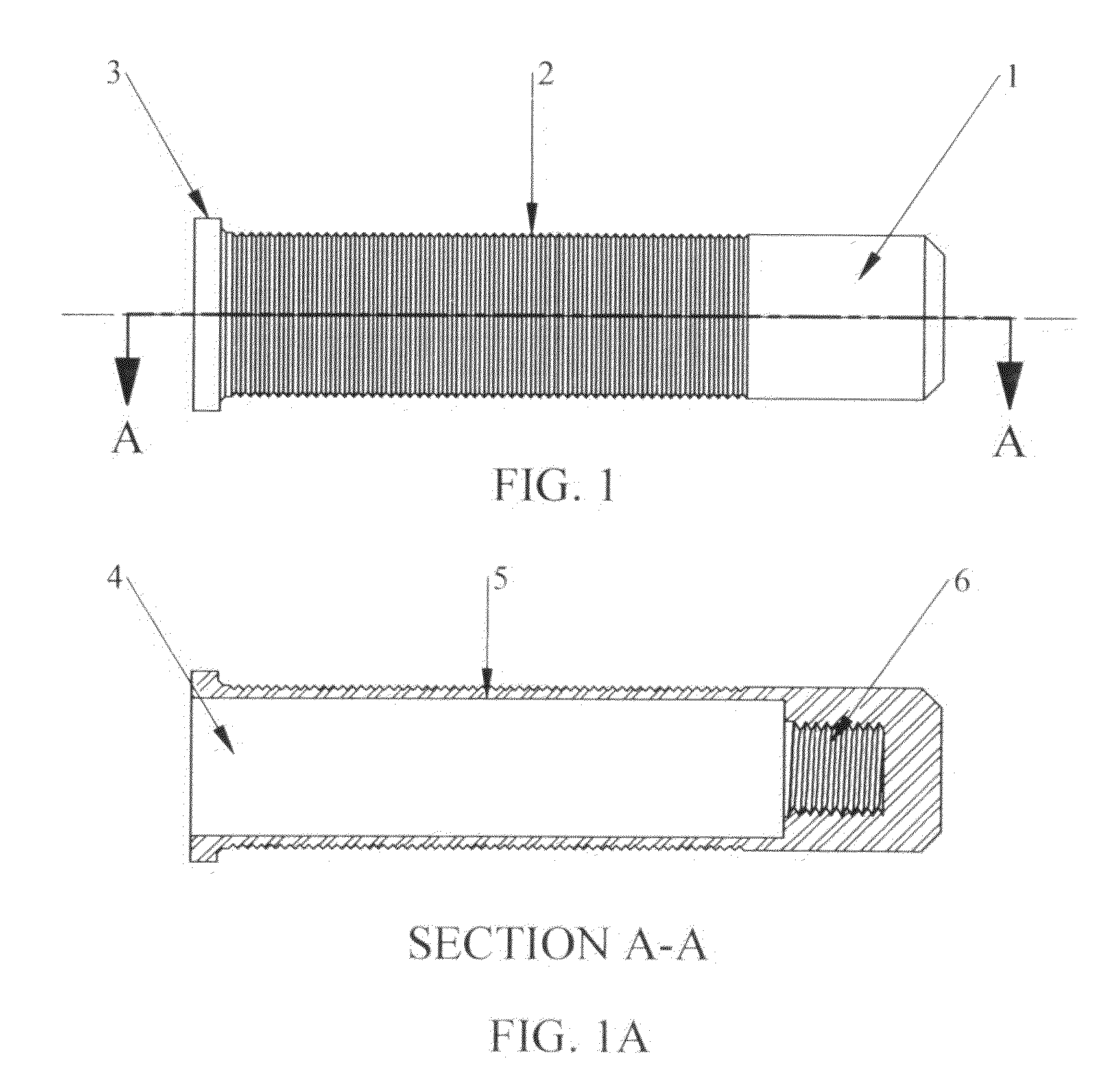
[0029]In referring to the drawings; and in particular to FIG. 1, the tube plug 1 is a cylindrical housing member that can be made of but not limited to the following materials: high strength steel, stainless steel, brass, titanium, and other highly engineered composite materials, that can be expanded using high pressure hydro-expansion tooling and techniques. It is sized for insertion within the end portion of a tube or an annular bore in a metal sheet i.e. tube-sheet, for a boiler, condenser, and other type heat exchanger. A portion of the outer surface of the plug 1 may or may not have concentric ridges and grooves 2 to grip the inside of the tube and create a seal, and may or may not have a flange 3 located at one end to control the depth of plug insertion into the tube. The plug 1 has an axial blind bore 4 comprising a smooth portion 5 which may or may not communicate with smaller diameter threaded portion 6. This threaded portion 6 when included is used for attaching various pl...


PUM

PropertyMeasurementUnit
pressureaaaaaaaaaa
pressureaaaaaaaaaa
pressuresaaaaaaaaaa

Abstract

A hydraulically installed tube plug with or without O.D surface enhancements and plug installation tooling, high pressure fluid system and method. The invention stops leaks in tubes with a plug that utilizes controlled high pressure fluid within the plug itself to radially expand the plug in place. Other plugs and plugging systems rely on mechanical methods for setting the plugs in the tubes with little or no control on the radial pressure applied to the tube. This lack of radial pressure control can result in a tubesheet ligament being over stressed (plastically deformed) or not enough pressure applied to stop the leak. The plug high pressure expansion tooling is designed with built in safety components that allow high pressure hydraulic expansion methods to be used safely in blind holes. The high pressure fluid system's design allows it to be used in hazardous environments.

Description

CROSS REFERENCE TO RELATED APPLICATION[0001]This non-provisional patent application claims priority to the provisional patent application having Ser. No. 61 / 396,978, having filing date Jun. 4, 2010.FIELD OF THE INVENTION[0002]This invention relates to means for hydraulically installing a tube plug within transfer tubes that are found in boilers, condensers, and other type heat exchangers, and relates to plug installation techniques, and their system and method.BACKGROUND OF THE INVENTION[0003]The present invention relates generally to tube plugs and plug installation techniques and more particularly to thimble type plugs and the use of high pressure expansion mandrel plug installation tooling and technique to stop leaks in tubes found in boilers, condensers and other shell-and-tube type heat exchangers.[0004]Some types of tube plugs used are tapered fiber (wooden or composite material) type plugs, one piece tapered metal plugs, two-piece metal tapered pin and collar plugs, multi-pie...

Claims


Application Information

Patent Timeline
Patent Type & Authority Patents(United States)
IPC IPC(8): F16L55/10F16L55/13
CPCF16L55/13
Inventor WASSON, RUSSELL D.
Owner HYDROPRO
Why Eureka
Try Eureka