Non-isolating circuit assembly and lamp using the same

a technology of non-isolating circuits and lamps, which is applied in the direction of lighting apparatus, light sources, lighting and heating apparatus, etc., can solve the problems of reducing the energy-saving effect of light-emitting diodes, reducing the brightness and lifetime of light-emitting diodes, and significant energy consumption associated with conventional illumination techniques, etc., to achieve small heat dissipation structures, non-isolating circuits, and increasing insulation distances

Inactive Publication Date: 2015-05-12
EDISON-OPTO
View PDF14 Cites 5 Cited by
  • Summary
  • Abstract
  • Description
  • Claims
  • Application Information

AI Technical Summary

Benefits of technology

[0010]The invention provides an improved non-isolating circuit assembly. In the non-isolating circuit assembly of the invention, an inwardly-reduced platform is disposed at the top of a heat sink, a circular supporting member is disposed around the inwardly-reduced platform, and a thermal insulation pad having an area larger than that of the inwardly-reduced platform is disposed on the inwardly-reduced platform and the circular supporting member. Through such a configuration, the insulation distance between a substrate that is disposed on the thermal insulation pad and the heat sink and measured by passing around the thermal insulation pad is increased. Therefore, the invention can achieve the purpose of increasing insulation distance without enlarging the size of the thermal insulation pad and still can achieve the effect of withstanding voltage. As a result, the invention may be used in small heat-dissipating structures. Moreover, the invention can use a thin thermal insulation pad and it is not necessary to employ a thick film forming method to increase the insulation distance, so that the thermal resistance between the substrate and the heat sink can be reduced and the ability to conduct heat and dissipate heat can be significantly improved. Furthermore, the invention allows of the continued use of the conventional aluminum heat sink for conducting electricity and heat. Compared with thermal plastic, the conventional aluminum heat sink has a higher thermal conduction and better performance of withstanding voltage.
[0014]In an embodiment of the invention, the contour of the inner edge of the circular supporting member and that of the outer edge of the inwardly-reduced platform are complementary, and the inner edge of the circular supporting member and the outer edge of the inwardly-reduced platform are tightly fit.

Problems solved by technology

There is a significant amount of energy consumption associated with conventional illumination techniques.
Failure to sufficiently decrease the junction temperature will result in the brightness and lifetime of light-emitting diode lamps to be greatly reduced.
Moreover, not only is the energy-saving effect of the light-emitting diode lamps reduced, but also, the reliability of the light-emitting diode lamps is directly impacted when the junction temperature is not sufficiently reduced.
In some instances, serious light attenuation performance occurs and / or the light-emitting diode lamps may even fail.
Due to the small size of heat-dissipating devices in some existing lamps, only non-isolating fixed current driving circuits with a small size can be used, and it is not possible to use isolating circuits (e.g., a converter).
If dangerous situations are encountered, such as exposure to lightning strikes (a non-human factor) or high voltage caused by an unstable power system (a human factor), the lamp using the non-isolating fixed current driving circuit will not be able to meet safety regulations such as CE (European Conformity), CUL (Product Safety Listed, Canada), etc.
That is, although plastic or other insulation materials can be used around the edges of a non-isolating fixed current driving circuit for isolation purposes, a circuit outputting terminal and a heat-conducting substrate make the non-isolating fixed current driving circuit a dangerous electrified body.

Method used


Image

  • Non-isolating circuit assembly and lamp using the same
  • Non-isolating circuit assembly and lamp using the same
  • Non-isolating circuit assembly and lamp using the same

Examples


Embodiment Construction

[0027]Reference will now be made in detail to the present embodiments of the invention, examples of which are illustrated in the accompanying drawings. Wherever possible, the same reference numbers are used in the drawings and the description to refer to the same or like parts.

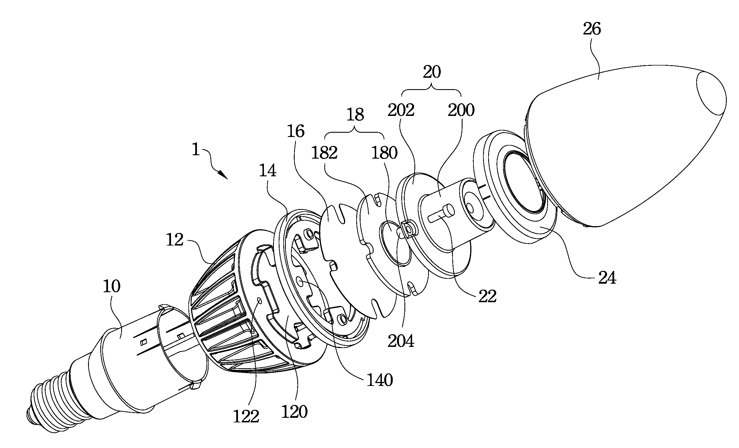
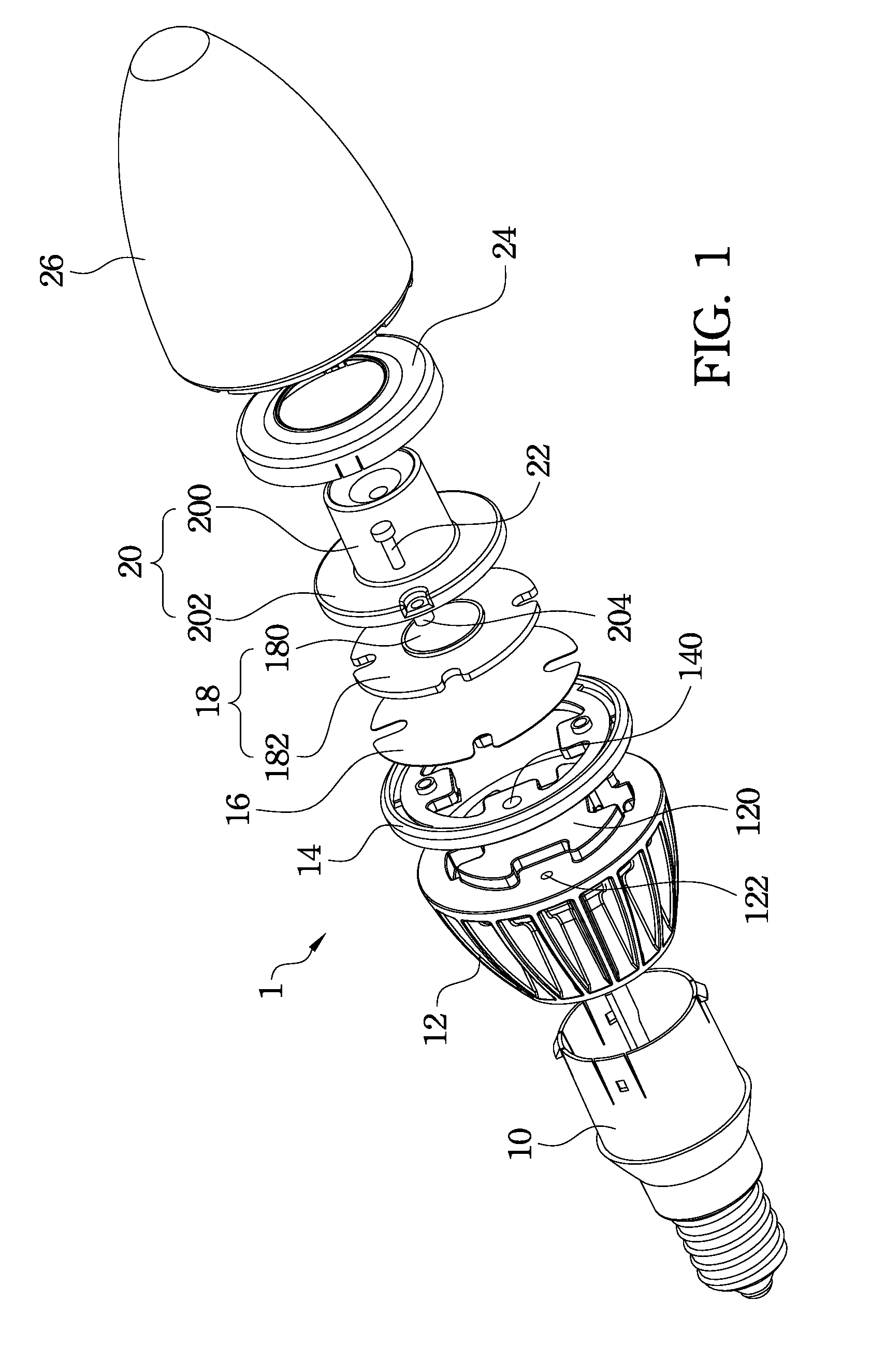
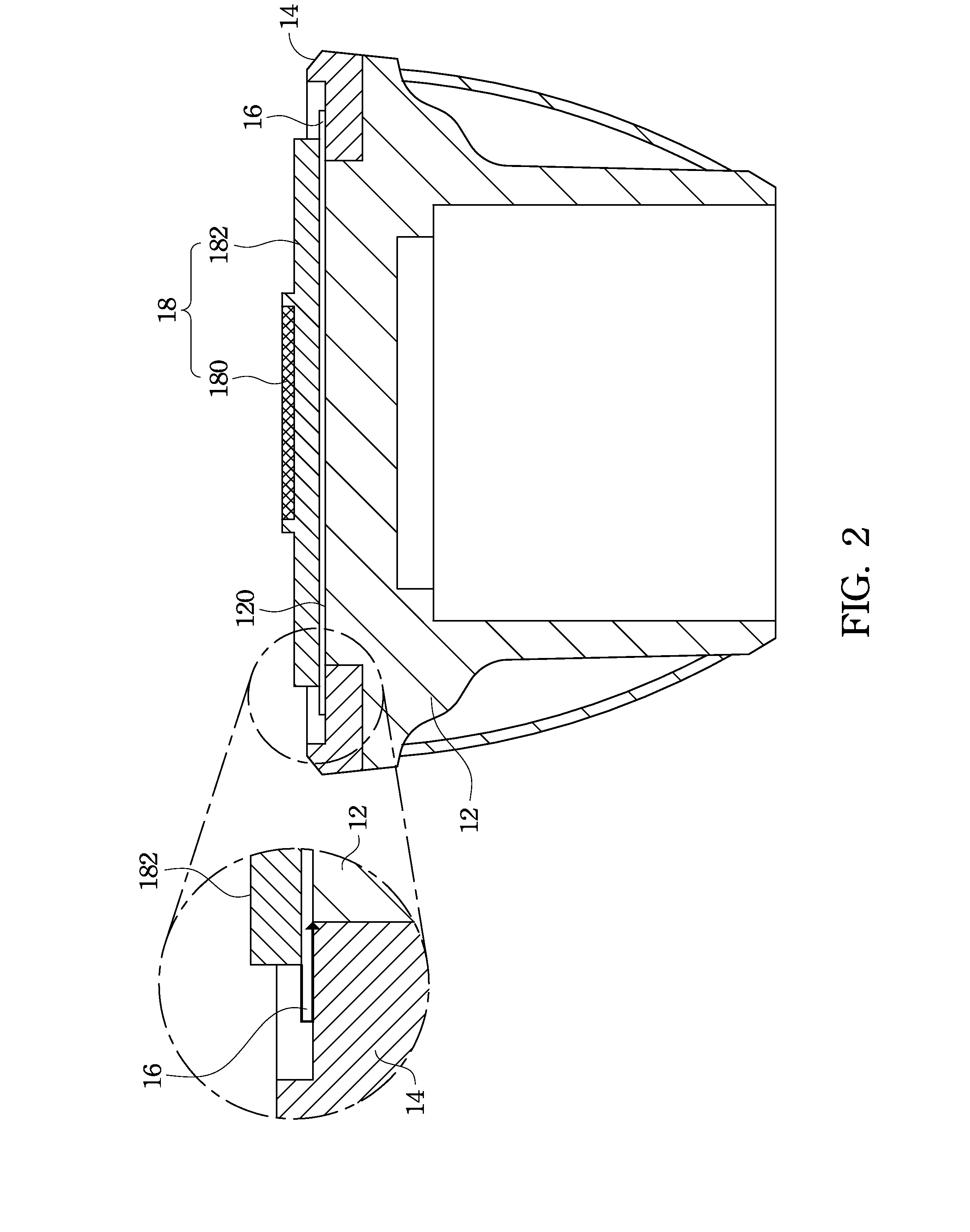
[0028]An improved lamp is provided. Specifically, in the lamp of the invention, an inwardly-reduced platform is disposed at the top of a heat sink, a circular supporting member is disposed around the inwardly-reduced platform, and a thermal insulation pad having an area larger than that of the inwardly-reduced platform is disposed on the inwardly-reduced platform and the circular supporting member. Through such a configuration, the insulation distance between a substrate that is disposed on the thermal insulation pad and the heat sink and measured by passing around the thermal insulation pad is increased. Therefore, the invention can achieve the purpose of increasing insulation distance without enlarging the s...


PUM


Abstract

A non-isolating circuit assembly includes a heat sink, a circular supporting member, a thermal insulation pad, and a light emitter. The heat sink has an inwardly-shrank platform. The circular supporting member is disposed around the outer edge of the inwardly-shrank platform. The thermal insulation pad is disposed on the inwardly-shrank platform and the circular supporting member. The area of the thermal insulation pad is larger than that of the inwardly-shrank platform, and the circular supporting member supports the outer edge of the thermal insulation pad. The light emitter is disposed on the thermal insulation pad.

Description

RELATED APPLICATIONS[0001]This application claims priority to Taiwan Application Serial Number 100139401, filed Oct. 28, 2011, which is herein incorporated by reference.BACKGROUND[0002]1. Field of Invention[0003]The present invention relates to a non-isolating circuit assembly and a lamp using the same, and more particularly, to a non-isolating circuit assembly and a lamp using the same, in which the insulation distance of internal circuits is increased through use of the non-insolating circuit assembly.[0004]2. Description of Related Art[0005]There is a significant amount of energy consumption associated with conventional illumination techniques. As a result, the development of techniques to realize lighting energy savings is one of the most important areas of new energy technology research. High-power and high-brightness light-emitting diodes, which are semiconductor light sources, are increasingly being used. Light-emitting diodes have many advantages including high luminous effi...

Claims


Application Information

Patent Timeline
Patent Type & Authority Patents(United States)
IPC IPC(8): F21V29/00F21K99/00
CPCF21K9/135F21K9/00F21V29/70F21V29/89F21V29/22F21V29/15F21K9/232
Inventor LEE, HSUAN-HSIEN
Owner EDISON-OPTO
Why Eureka
Try Eureka