High frequency square-wave power distribution system

a power distribution system and high frequency square wave technology, applied in the direction of electric variable regulation, process and machine control, instruments, etc., can solve the problems of square wave at the rectifier being compromised, voltage may droop, etc., to achieve precise input voltage, precise voltage magnitude, and low voltage drop

Inactive Publication Date: 2015-05-12
HERBERT EDWARD
View PDF6 Cites 17 Cited by
  • Summary
  • Abstract
  • Description
  • Claims
  • Application Information

AI Technical Summary

Benefits of technology

[0012]If a full-bridge switch has a precise input voltage, a tightly coupled input capacitor and uses MOSFET switches with a very low voltage drop, the resulting square-wave also has a precise voltage magnitude. If the switching is 100 percent duty-ratio (50-50 for each switching cycle) and the switch drive is crisp, the square-wave will be clean and have crisp transitions with minimal rounding. When such a square-wave is rectified, the resulting dc will be clean and require very minimal filtering. Fast switching not only ensures a clean wave-form, it also reduces crossover power loss for improved efficiency. U.S. Pat. No. 6,992,520 teaches a method for the very fast switching of MOSFETs, which are commonly used in full-bridge switches and rectifiers.

Problems solved by technology

However, if there is significant leakage inductance in the circuit between the full-bridge switch and the rectifier, the square-wave at the rectifier may be compromised, with rounded transitions showing characteristic exponential rise and fall times, and the voltage may droop as the load is increased.

Method used


Image

  • High frequency square-wave power distribution system
  • High frequency square-wave power distribution system
  • High frequency square-wave power distribution system

Examples


Embodiment Construction

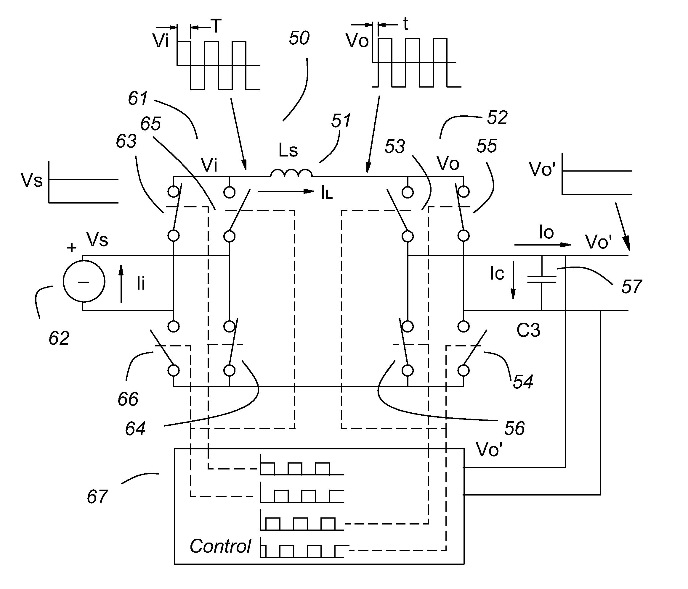
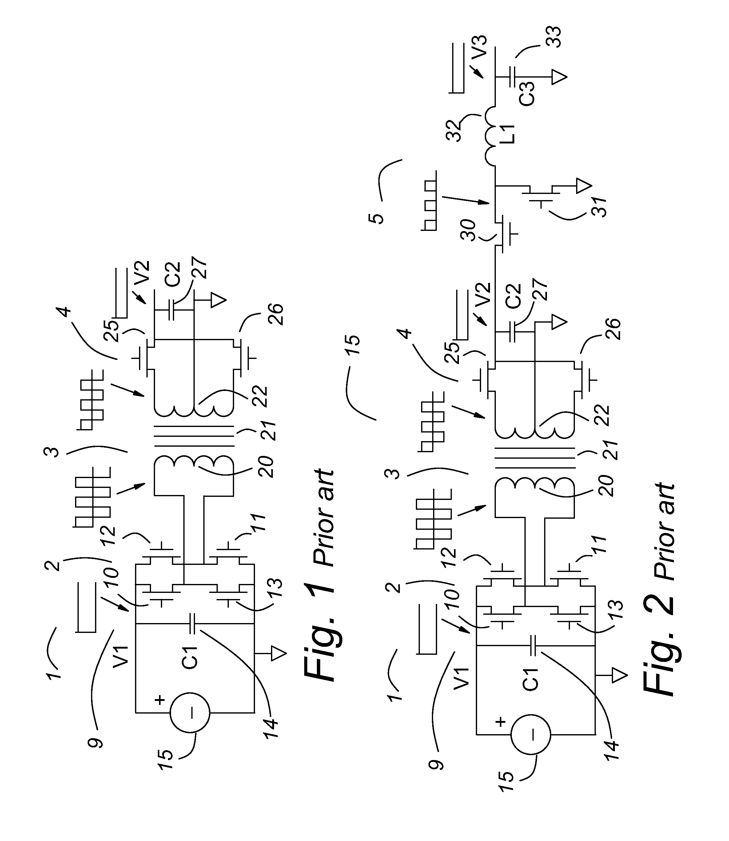
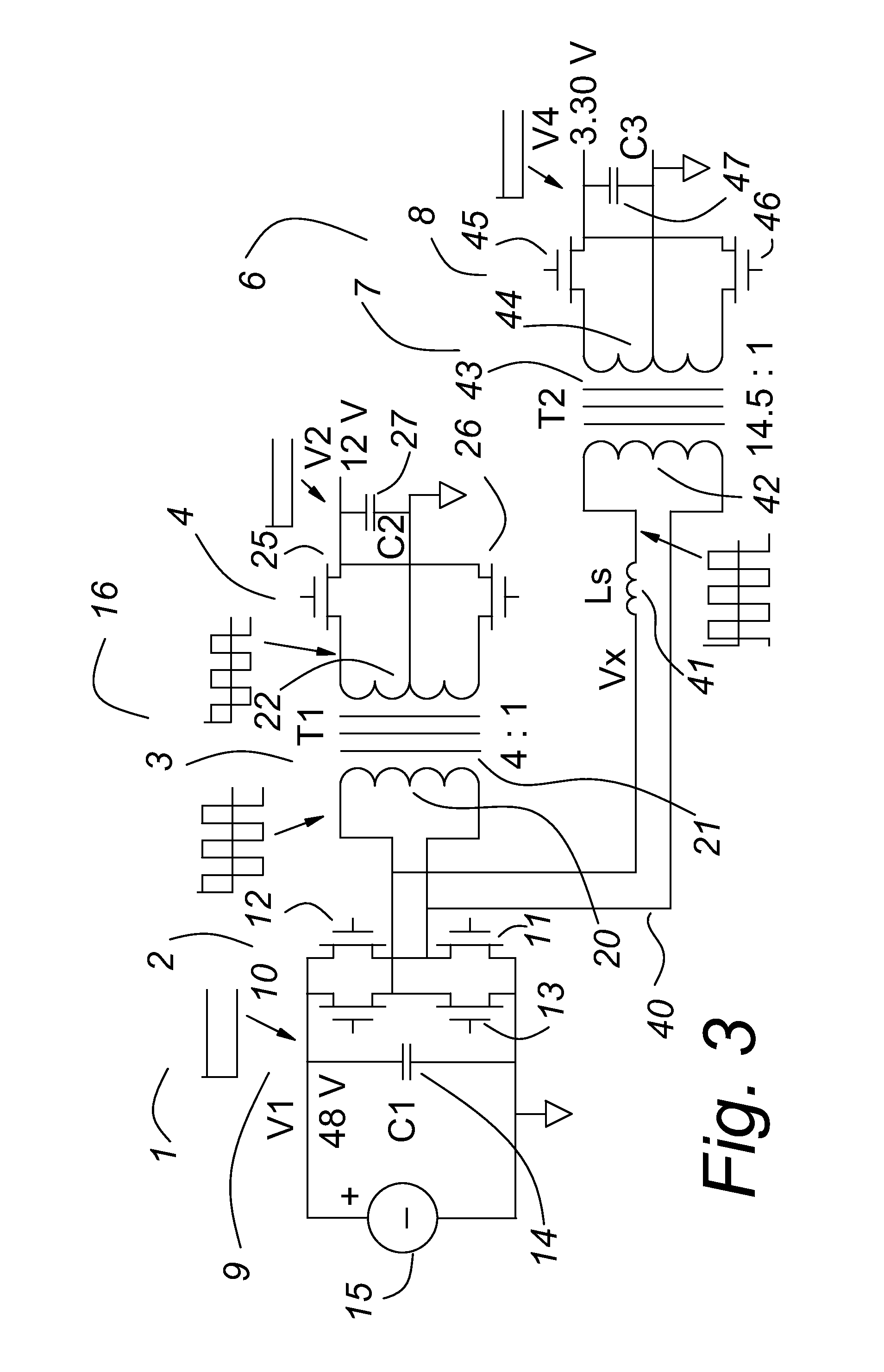
[0061]FIG. 1 shows an example of a common power converter circuit often called a “dc-dc transformer.” Of course, all transformers use ac excitation, but a high frequency transformer together with full-bridge switches on its input and rectifying switches on its output as a whole circuit accepts a dc input voltage and provides a dc output voltage, thus its common name.

[0062]In FIG. 1, a dc-dc transformer 1 comprises a full-bridge switch 2, a transformer 3 and a rectifier 4. An input capacitor 14 and an output capacitor 27 are usually included as filter capacitors. A square-wave voltage source 9 comprises a dc voltage source 15 and the full-bridge switch 2, comprises four switches 10-13 shown as MOSFETs, as an example, not a limitation. The transformer 3 comprises a primary winding 20, a transformer core 21 and a secondary winding 22. The rectifier 4 is shown as a push-pull rectifier, as an example, not a limitation, and comprises two switches 25 and 26, shown as MOSFETs, as an example...


PUM


Abstract

A minimalized power converter has a square-wave voltage source operating at 100 percent duty-ratio, a series inductance and a rectifier. A high frequency square-wave power distribution system comprises a plurality of minimalized power converters connected by a common ac power distribution link. Because the ac power distribution link carries current at a high frequency, the square-wave may be degraded by the stray inductance with distance. Re-squaring circuits along the length of the ac power distribution link operating synchronously restore and preserve the integrity of the square-wave. The minimalized power converter is very flexible and has very fast dynamic response, being able to make very fast controlled current transitions from any current to any other current, including zero or current reversal (same voltage, opposite current flow).

Description

[0001]This patent application is a continuation in part of Ser. No. 12 / 704,862, (now abandoned) filed Feb. 12, 2010, and entitled “Multi-port Variable Transformer.” This patent application is incorporated herein by reference.[0002]This patent application is a continuation in part of Ser. No. 61 / 488,721, filed May 21, 2011, and entitled “Minimalized Power Converter.” This patent application is incorporated herein by reference, and priority is claimed to its filing date.[0003]Reference is made to U.S. provisional patent application Ser. No. 61 / 349,289, filed May 28, 2010 and entitled “Interleaved Current Doubler with Common Mode Capacitor”.[0004]Reference is made to U.S. patent application Ser. No. 13 / 118,676, filed May 31, 2011 and entitled “Interleaved Current Doubler with Common Mode Capacitor”, now U.S. Pat. No. 8,310,329, issued Nov. 13, 2012 and now entitled: Interleaved Common Mode Transformer with Common Mode Capacitors.[0005]Reference is made to a U.S. Pat. No. 7,119,648, iss...

Claims


Application Information

Patent Timeline
Patent Type & Authority Patents(United States)
IPC IPC(8): H02M3/335
CPCH02M3/33507H02M3/33561H02M3/33592H02J1/10H02J5/00Y02B70/10
Inventor HERBERT, EDWARD
Owner HERBERT EDWARD
Why Eureka
Try Eureka