Filter module and system having spirally wound membrane filters, and method for the production thereof
- Summary
- Abstract
- Description
- Claims
- Application Information
AI Technical Summary
Benefits of technology
Problems solved by technology
Method used
Image

Examples
Embodiment Construction
[0010]It is the object of the invention to overcome the above-mentioned disadvantages and to provide a filter module having a spiral winding, the filter module having high pressure resistance and large individual filter layer surfaces and being back-flushable and suitable for use in commercial filtration systems.
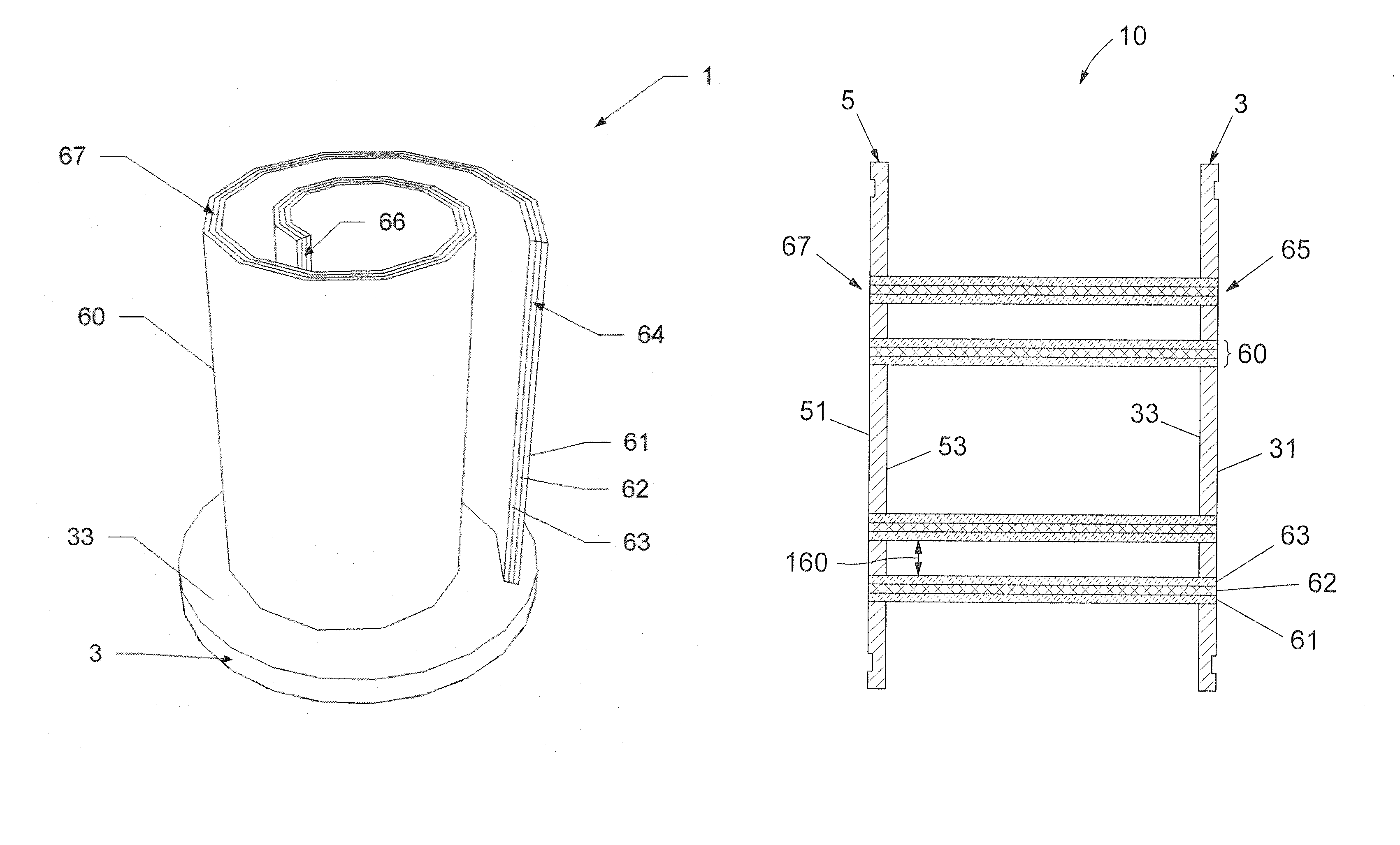
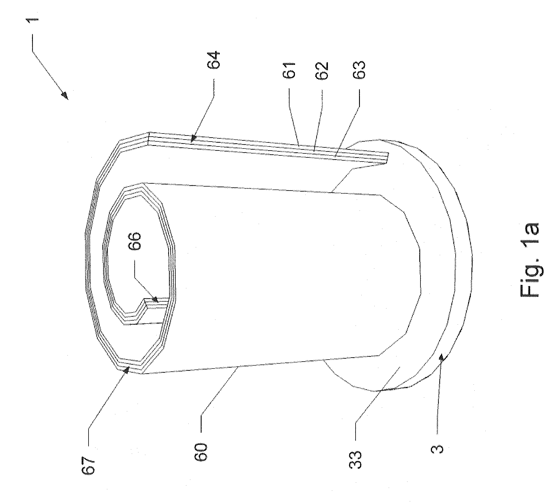
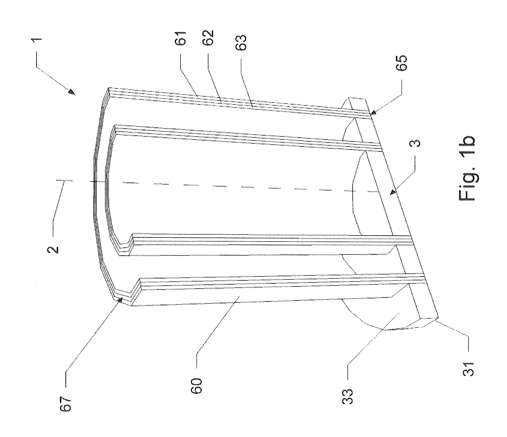
[0011]This object is achieved by a filter module which comprises one or more flat filter elements wound spirally about an axis, a first end wall and optionally a second end wall, wherein each flat filter element comprises two filter membranes and a drainage layer arranged between the filter membranes; each flat filter element has first and second edge regions which run substantially in the direction of the axis and are sealed in a fluid-tight manner; each flat filter element has a third edge region which is connected to the first end wall; the third edge region is open on an outer side of the first end wall; the third edge region is sealed in a fluid-tight manner in relation...
PUM
| Property | Measurement | Unit |
|---|---|---|
| Length | aaaaa | aaaaa |
| Length | aaaaa | aaaaa |
| Pressure | aaaaa | aaaaa |
Abstract
Description
Claims
Application Information
 - R&D
- Intellectual Property
- Life Sciences
- Materials
- Tech Scout
- Unparalleled Data Quality
- Higher Quality Content
- 60% Fewer Hallucinations
Browse by: Latest US Patents, China's latest patents, Technical Efficacy Thesaurus, Application Domain, Technology Topic, Popular Technical Reports.
© 2025 PatSnap. All rights reserved.Legal|Privacy policy|Modern Slavery Act Transparency Statement|Sitemap|About US| Contact US: help@patsnap.com