Pulsation damper

a technology of damper and pulsating shaft, which is applied in the direction of liquid fuel engines, fuel injecting pumps, machines/engines, etc., can solve the problems of degrading the adjustment accuracy of the amount of fuel, and achieve the effects of reducing thickness, low rigidity, and expanding the pressure rang

Inactive Publication Date: 2015-06-16
TOYOTA JIDOSHA KK
View PDF23 Cites 12 Cited by
  • Summary
  • Abstract
  • Description
  • Claims
  • Application Information

AI Technical Summary

Benefits of technology

[0009]Accordingly, it is an objective of the present invention to provide a pulsation damper that, despite a simple structure, is capable of maintaining high reliability at a joint section of a diaphragm that is integrated with a high-pressure fuel pump and operates together with a gas chamber to inhibit pressure pulsations of fuel.
[0013]The stress generated in the diaphragm by pressure applied to the displacement section thereof concentrates on a part that is continuous to the cylindrical circumferential section, which extends in a direction perpendicular to the displacement section, that is, on the periphery of the displacement section. In this regard, the projection that has an arcuately bulging cross-sectional shape in the direction opposite to the support member is formed on the periphery of the displacement section, on which stress is concentrated. Also, the remainder of the displacement section is formed to be flat to increase the area for receiving stress concentrated on the periphery. This relaxes the stress acting on the diaphragm. This allows the reliability at the joint section to be maintained at a high level, and therefore further improves the pressure tolerance as a pulsation damper.
[0015]According to this configuration, the pump cover of the high-pressure fuel pump, to which the pulsation damper is attached, is used as the support member for the diaphragm of the pulsation damper. Thus, compared to a configuration with an additional support member for supporting the diaphragm, the number of components of the high-pressure fuel pump is reduced, and the size of the high-pressure fuel pump is minimized.
[0016]In accordance with one aspect of the present invention, the pump cover partially has a low rigidity section with low rigidity.
[0017]According to this configuration, the low rigidity section of the pump cover correspondingly increases the amount of displacement of the pump cover in response to the pressure applied to the displacement section of the diaphragm. That is, in addition to the diaphragm having the displacement section, the cover serving as the support member can absorb pressure changes in fuel, in other words, pressure pulsation. This increases the range of pressure pulsation that can be absorbed by the entire pulsation damper, and therefore improves pulsation reducing performance.
[0019]According to these configurations, it is possible to expand the range of pressure that can be absorbed by the pulsation damper simply by reducing the thickness in a part of the material of the pump cover to form a low rigidity section.

Problems solved by technology

This contributes to degradation of the adjustment accuracy of the amount of fuel sent from the high-pressure fuel pump to the delivery pipe.

Method used


Image

  • Pulsation damper
  • Pulsation damper
  • Pulsation damper

Examples


Embodiment Construction

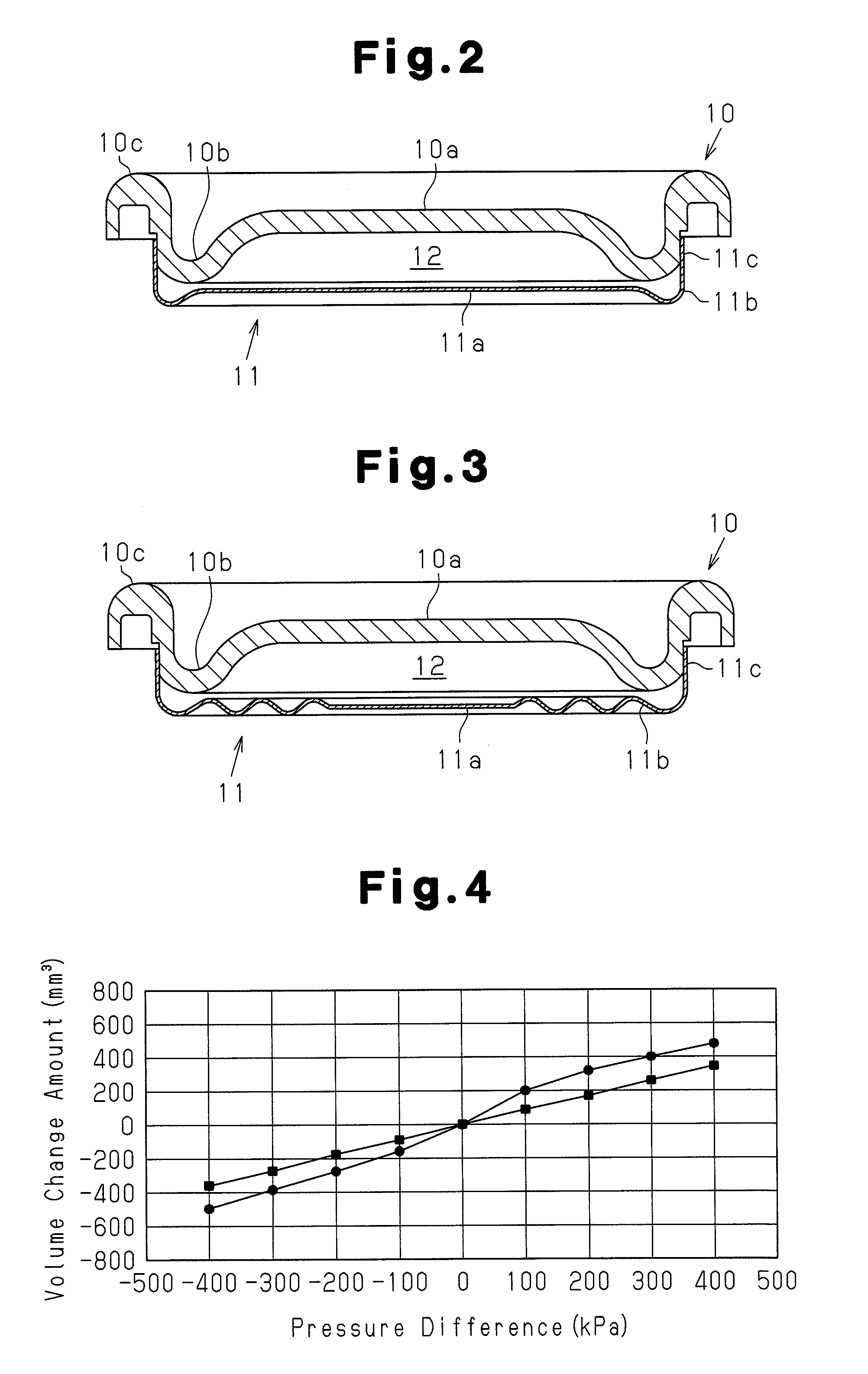
[0030]A pulsation damper according to one embodiment of the present invention will now be described with reference to FIGS. 1 and 2.

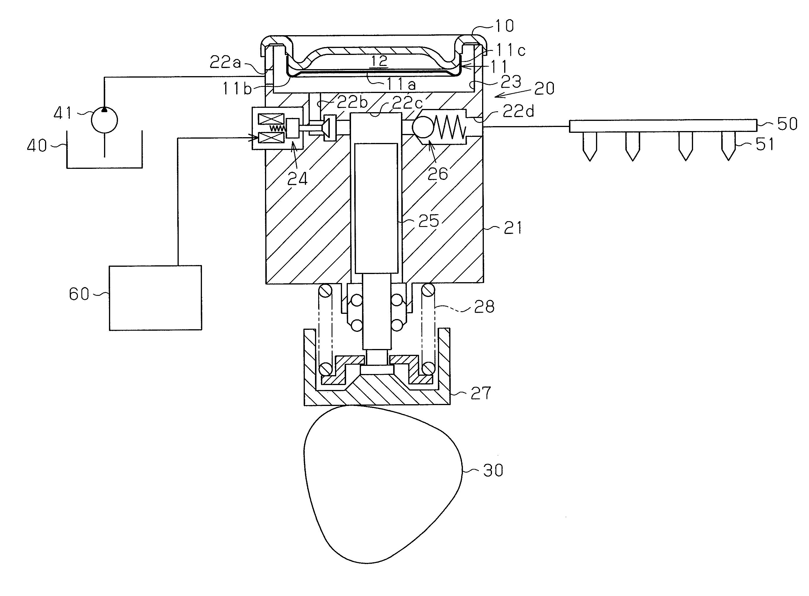
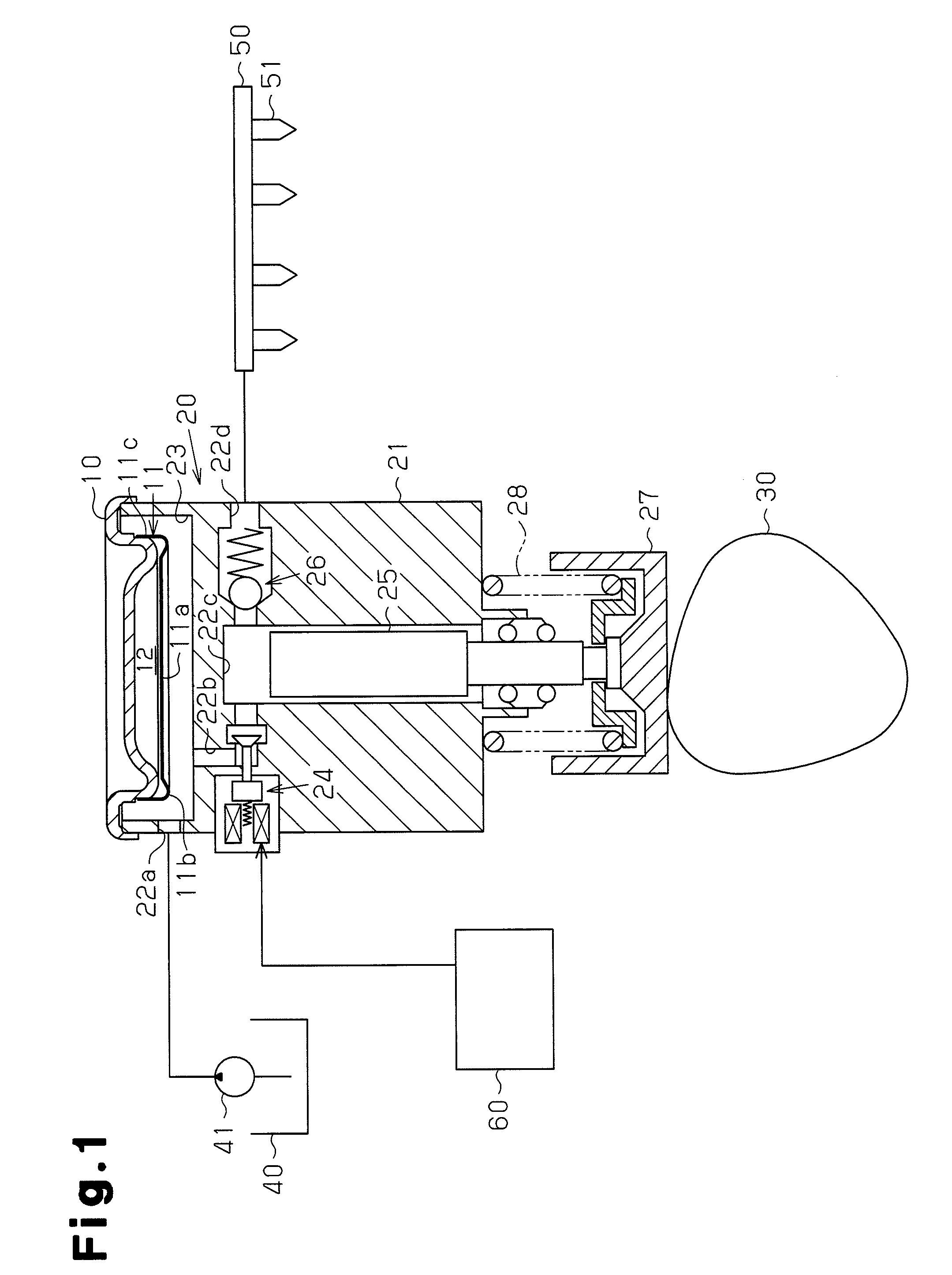
[0031]FIG. 1 schematically shows a high-pressure fuel pump 20 having a pulsation damper according to the present embodiment and a surrounding structure, or a fuel supply system. The high-pressure fuel pump 20 is attached, for example, to a cylinder head cover of an in-cylinder injection internal combustion engine that uses gasoline as fuel.

[0032]As shown in FIG. 1, the high-pressure fuel pump 20 has a housing 21, in which a fuel inlet 22a and a fuel chamber 23 are provided. Fuel that has been pumped by a fuel pump (feed pump) 41 flows into the fuel inlet 22a. The fuel is then temporarily retained in the fuel chamber 23. Also, fuel retained in the fuel chamber 23 is sent to a pressurizing chamber 22c in a cylinder via a fuel communication passage 22b and an electromagnetic valve 24. The fuel is then pressurized by a plunger 25 in the pressurizing chamber...


PUM


Abstract

A pulsation damper mounted in a fuel chamber (23) of a high-pressure fuel pump (20) is provided with a diaphragm (11) having a flat section (11a) displaced when fuel pressure is applied thereto, a pump cover (10) for supporting the diaphragm (11), and a gas chamber (12) formed by the diaphragm (11) and the pump cover (10). Pressure pulsation occurring in the fuel chamber (23) is suppressed by displacement of the flat section (11a). The diaphragm (11) is formed in a closed-bottomed tubular shape with the flat section (11a) located at the bottom and has a projection (11b) provided to the periphery of the flat section (11a) and projecting to the side opposite to the pump cover (10). A tubular peripheral section extending from the outer periphery of the projection (11b) so as to be vertical to the flat section (11a) is fitted over the pump cover (10). The externally fitting portion of the tubular peripheral section is a joint section (11c) joined to the pump cover (10).

Description

CROSS REFERENCE TO RELATED APPLICATION[0001]This application is a National Stage of International Application No. PCT / JP2009 / 055202 filed Mar. 17, 2009, the contents of all of which are incorporated herein by reference in their entirety.FIELD OF THE INVENTION[0002]The present invention relates to a pulsation damper, particularly to a pulsation damper that is integrally provided to a high-pressure fuel pump for feeding high pressure fuel to the delivery pipe of an in-cylinder injection internal combustion engine that uses gasoline as fuel, and reduces pulsations generated by the operation of the pump.BACKGROUND ART[0003]As is known, an in-cylinder injection internal combustion engine using gasoline as fuel includes a high-pressure fuel pump that receives fuel pumped up from a fuel tank by a fuel pump, pressurizes the fuel to a pressure higher than the discharge pressure of the fuel pump, and sends the pressurized fuel to a delivery pipe (high-pressure piping) connected to an injector...

Claims


Application Information

Patent Timeline
Patent Type & Authority Patents(United States)
IPC IPC(8): F02M69/46F02M55/04F02M59/44F04B53/00
CPCF02M55/04F02M59/44F04B53/003F02M2200/315
Inventor USUI, TAKASHITAKEUCHI, YOSHINORIYABUUCHI, TAKEYUKI
Owner TOYOTA JIDOSHA KK
Why Eureka
Try Eureka