System and method for reducing the complexity of performing broad-phase collision detection on GPUs

a broad-phase collision and detection system technology, applied in the field of parallel processing, can solve the problems of not achieving the effect of parallel processing, avoiding potentially significant computational effort, and certain other types of processing tasks, etc., and achieve the effect of substantially increasing computational efficiency

Active Publication Date: 2015-06-16
NVIDIA CORP
View PDF4 Cites 12 Cited by
  • Summary
  • Abstract
  • Description
  • Claims
  • Application Information

AI Technical Summary

Benefits of technology

[0011]One advantage of the disclosed method is that it enables broad phase collision detection to be performed using parallel spatial subdivision. The method may be implemented using one or more parallel processing units, each configured to execute multiple threads in parallel. Consequently, computational efficiency may be substantially increased relative to prior art techniques.

Problems solved by technology

Each object pair discarded in the broad phases saves potentially significant computational effort in the narrow phase.
However, certain other types of processing tasks, such as collision detection in physics simulations, have not benefited from parallel processing because known algorithms for performing collision detection include inherently serial operations.
In an application that processes large numbers of potentially colliding objects, the relative inefficiency of the broad phase of the collision detection algorithm can result in significant performance bottle necks.
In an application that combines tasks that benefit from parallel processing, such as graphics rendering, with collision detection tasks, the inefficiency associated with conventional, serialized collision detection can cripple the overall performance of the application, despite the benefits of parallel processing realized for a certain subset of tasks.

Method used


Image

  • System and method for reducing the complexity of performing broad-phase collision detection on GPUs
  • System and method for reducing the complexity of performing broad-phase collision detection on GPUs
  • System and method for reducing the complexity of performing broad-phase collision detection on GPUs

Examples


first embodiment

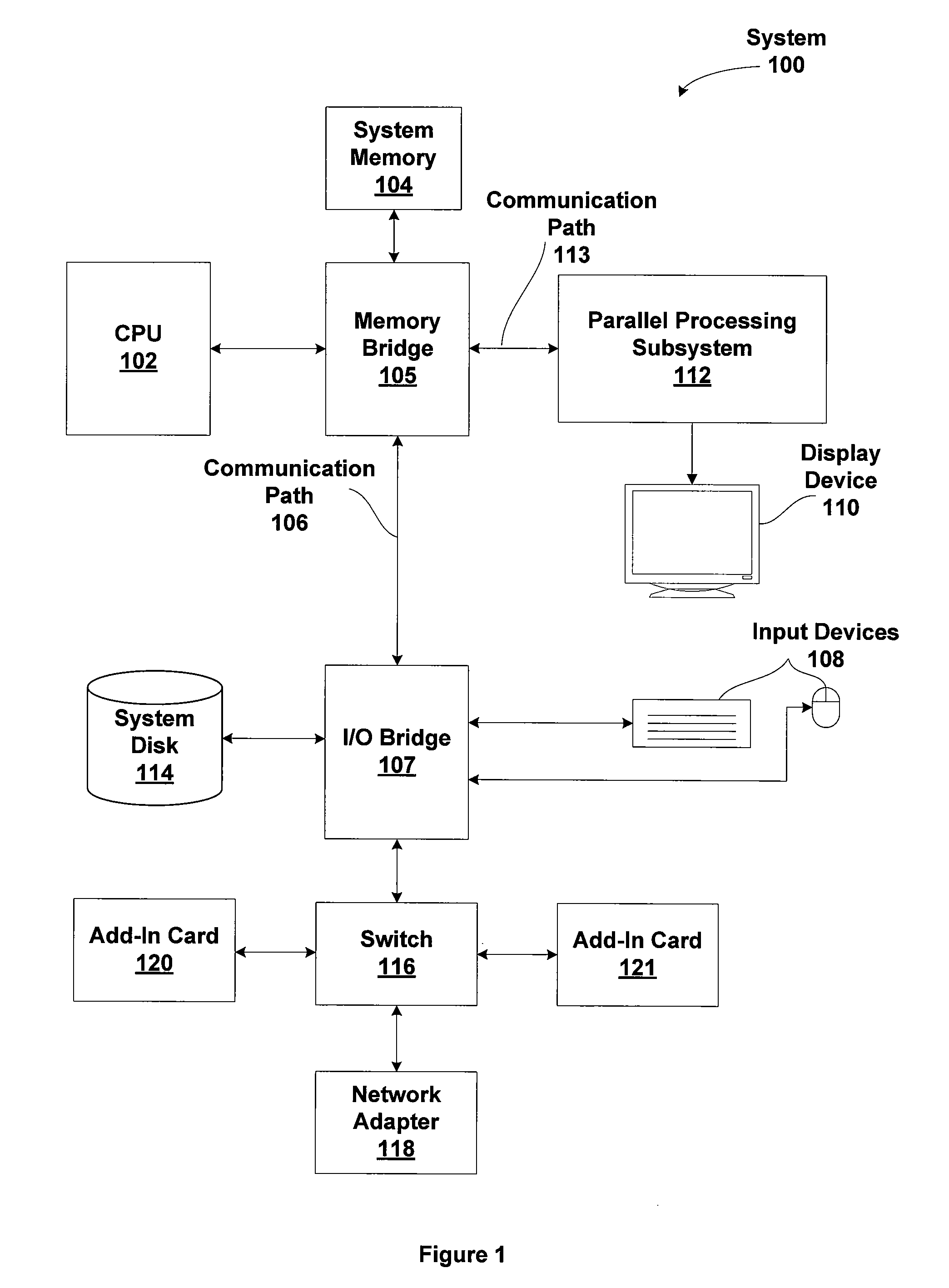
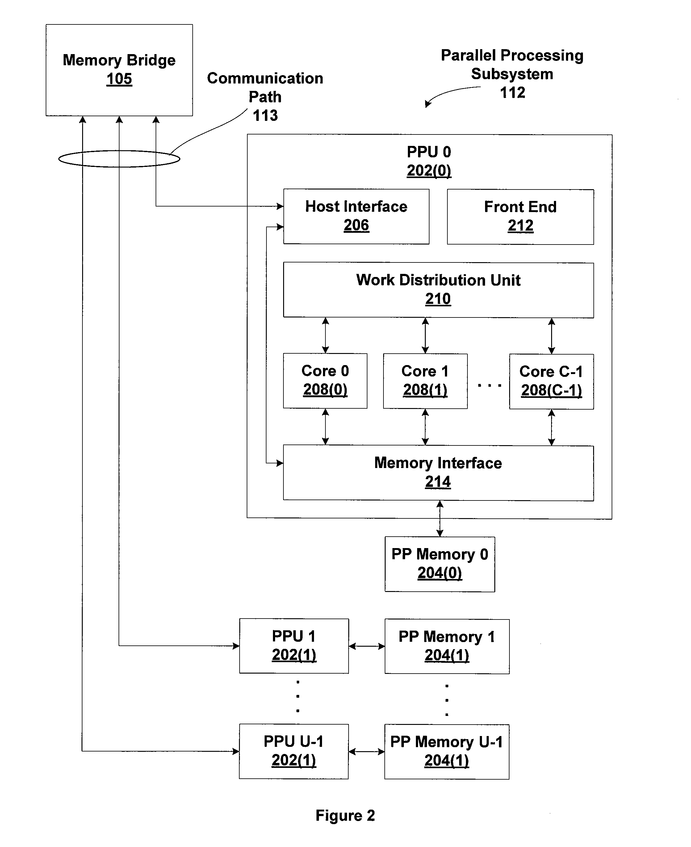
[0091]FIG. 12 is a flow diagram of method steps for performing broad-phase collision detection, according to the present invention. Although the method steps are described in conjunction with the systems of FIGS. 1, 2, and 3, persons skilled in the art will understand that any system that performs the method steps, in any order, is within the scope of the invention.

[0092]The method begins in step 1210, where a cell size is determined for uniformly partitioning the 3D coordinate system into one or more arrays of cubical cells. The cell size is defined as the length of each edge of a uniform cube within the array. The cell size should be at least 1.5 times the diameter of the largest bounding sphere to be processed. The radius of each bounding sphere is the square root of two times the radius of each object to be processed.

[0093]In step 1212, a cell ID array is initialized to allocate space that includes entries for each bounding sphere associated with each object to be processed. For...

second embodiment

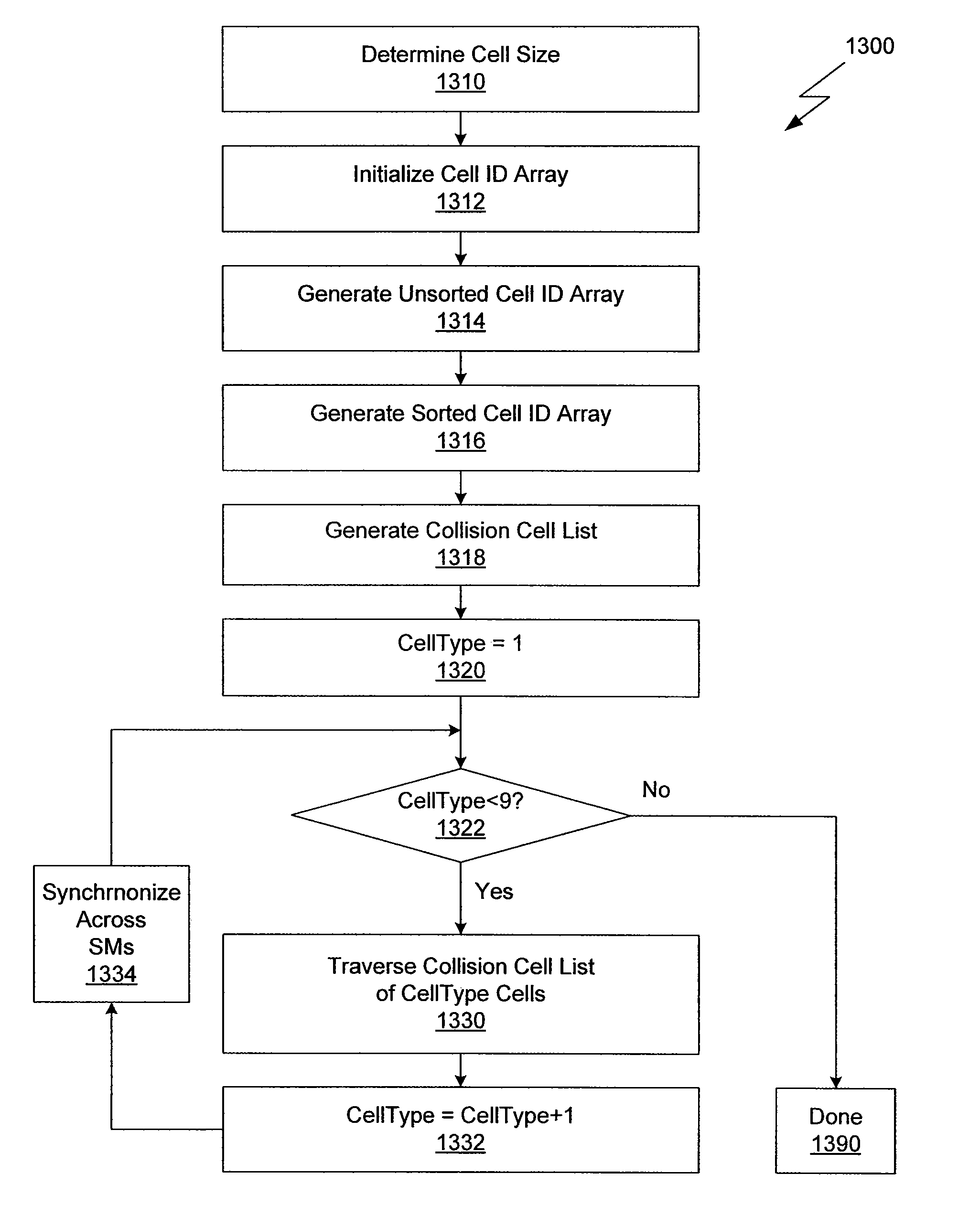
[0097]FIG. 13 is a flow diagram of method steps for performing collision detection analysis in multiple passes, according to the invention. Although the method steps are described in conjunction with the systems of FIGS. 1, 2, and 3, persons skilled in the art will understand that any system that performs the method steps, in any order, is within the scope of the invention.

[0098]The method begins in step 1310, where a cell size is determined for uniformly partitioning the 3D coordinate system into one or more arrays of cubical cells. The cell size is defined as the length of each edge of a uniform cube within the array. The cell size should be at least 1.5 times the diameter of the largest bounding sphere to be processed. The radius of each bounding sphere is the square root of two times the radius of each object to be processed.

[0099]In step 1312, a cell ID array is initialized to allocate space that includes entries for each bounding sphere associated with each object to be proces...


PUM


Abstract

One embodiment of the present invention sets forth a technique for efficiently performing broad phase collision detection using parallel spatial subdivision. The technique involves organizing candidate objects according to a hashed representation of each object centroid, constructing a cell identification (ID) array, sorting the cell ID array, creating a collision cell list, and traversing the collision cell list. The result is a candidate list of object groups that may collide, based on an initial assessment of spatial proximity. Whether a given pair of objects actually collides is determined by a precise narrow phase collision analysis.

Description

CROSS-REFERENCE TO RELATED APPLICATIONS[0001]This application claims the priority benefit of the U.S. provisional patent application having Ser. No. 60 / 953,169 and filed on Jul. 31, 2007. The subject matter of this provisional patent application is hereby incorporated herein by reference.BACKGROUND OF THE INVENTION[0002]1. Field of the Invention[0003]Embodiments of the present invention relate generally to parallel processing and more specifically to a system and method for reducing the complexity of performing broad-phase collision detection on GPUs.[0004]2. Description of the Related Art[0005]Collision detection is an important component of computer-based physics simulation, computer-aided design, molecular modeling, and other applications. Collision detection determines whether two or more three-dimensional (3D) objects interact through a collision. Most efficient implementations of collision detection use a two-phase approach, involving a first “broad” phase and a second “narrow...

Claims


Application Information

Patent Timeline
Patent Type & Authority Patents(United States)
IPC IPC(8): G06T15/00G06T13/00G06T17/00G06T15/30G09G5/00G06F15/08
CPCG06T17/00G06T17/005G06T2210/21G06T15/005G06T2200/28G06T7/13G06T1/20G06T15/80
Inventor LE GRAND, SCOTT M.
Owner NVIDIA CORP
Why Eureka
Try Eureka