Dry-etch for selective oxidation removal

a selective oxidation and dry-etching technology, applied in the direction of coatings, chemical vapor deposition coatings, electric discharge tubes, etc., can solve the problems that fewer dry-etching processes have been developed to selectively remove metals and/or their oxidation, and achieve the effect of slow removal of other exposed materials, reducing or substantially eliminating the number of ionically charged species

Active Publication Date: 2015-06-23
APPLIED MATERIALS INC
View PDF717 Cites 181 Cited by
  • Summary
  • Abstract
  • Description
  • Claims
  • Application Information

AI Technical Summary

Benefits of technology

[0005]Methods of selectively etching tungsten oxide relative to tungsten, silicon oxide, silicon nitride and / or titanium nitride are described. The methods include a remote plasma etch formed from a fluorine-containing precursor and / or hydrogen (H2). Plasma effluents from the remote plasma are flowed into a substrate processing region where the plasma effluents react with the tungsten oxide. The plasmas effluents react with exposed surfaces and selectively remove tungsten oxide while very slowly removing other exposed materials. In some embodiments, the tungsten oxide selectivity results partly from the presence of an ion suppression element positioned between the remote plasma and the substrate processing region. The ion suppression element reduces or substantially eliminates the number of ionically-charged species that reach the substrate.

Problems solved by technology

However, fewer dry-etch processes have been developed to selectively remove metals and / or their oxidation.

Method used


Image

  • Dry-etch for selective oxidation removal
  • Dry-etch for selective oxidation removal
  • Dry-etch for selective oxidation removal

Examples


first example

A First Example

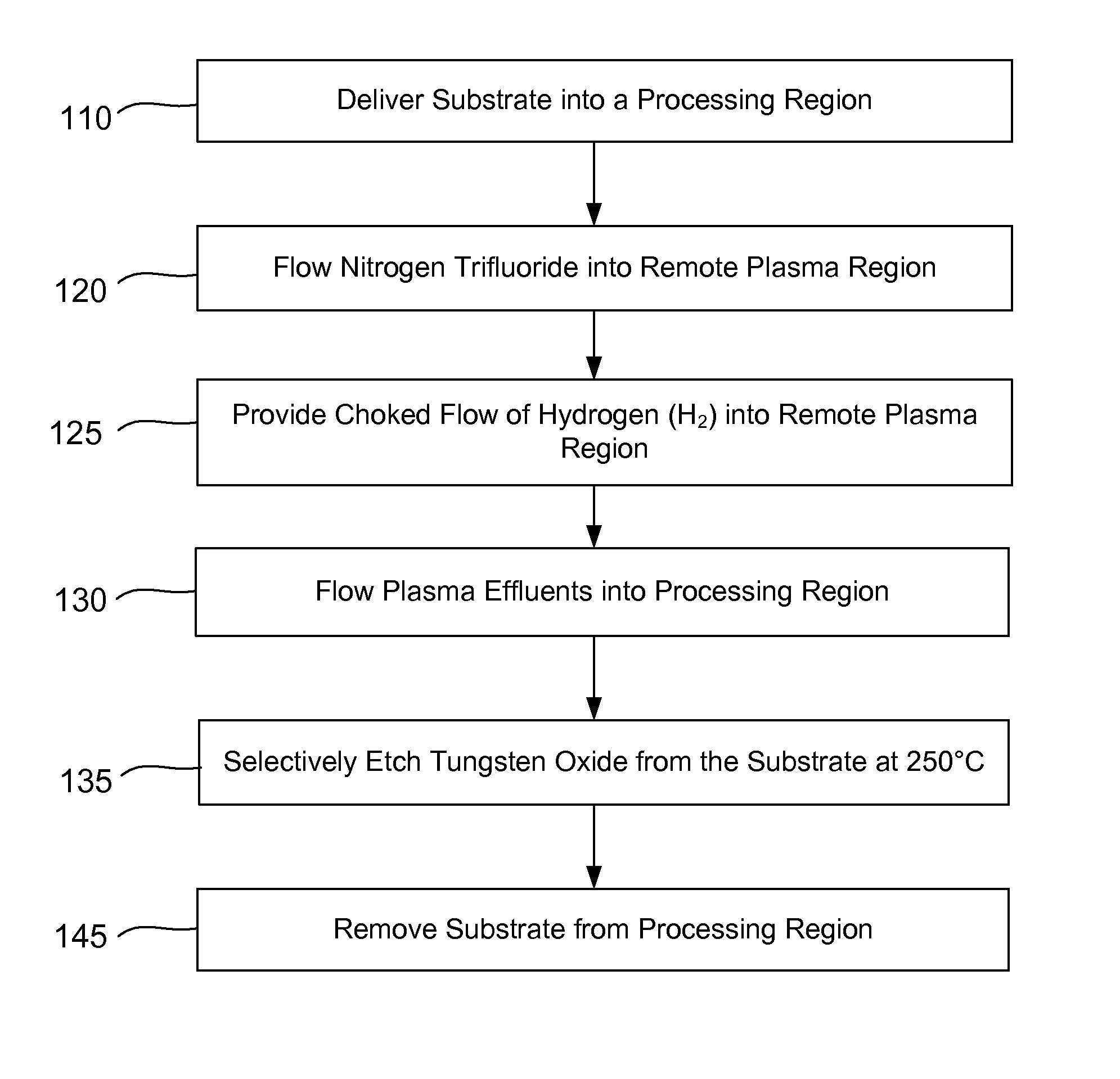
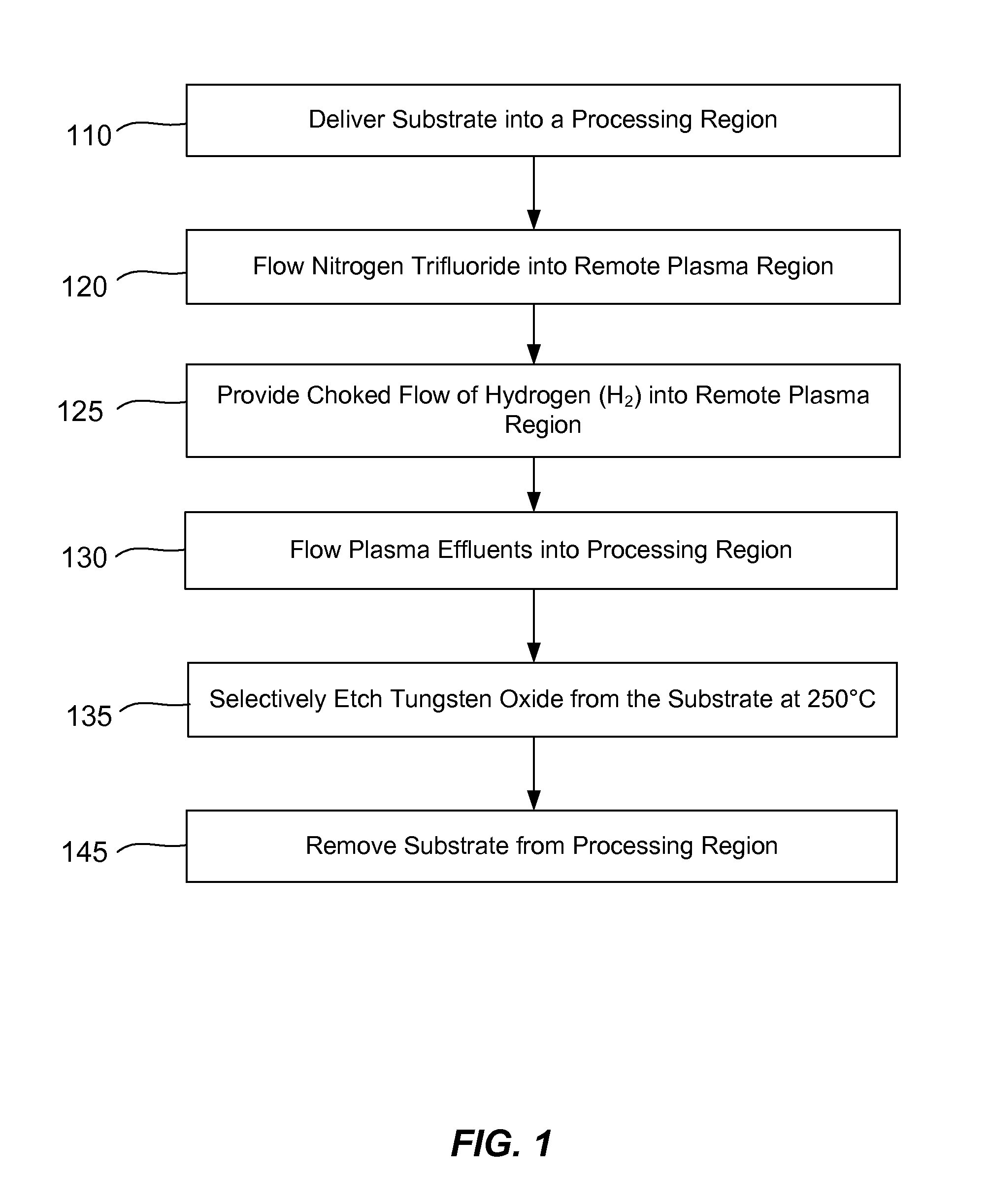
[0017]In order to better understand and appreciate the invention, reference is now made to FIG. 1 which is a flow chart of a tungsten oxide selective etch process according to disclosed embodiments. The tungsten oxide may have a variety of stoichiometries which may be determined by the method of forming the tungsten oxide. Prior to the first operation, tungsten oxide is formed on a substrate. The tungsten oxide may be in the form of a blanket layer on the substrate or it may reside in discrete regions of a patterned substrate surface. In either case, the tungsten oxide forms exposed surfaces of the surface of the substrate. The substrate is then delivered into a processing region (operation 110). In another embodiment, the tungsten oxide may be formed after delivering the substrate to the processing region, for example, by treating exposed regions of tungsten to a reactive oxygen source.

[0018]A flow of nitrogen trifluoride is introduced into a plasma region separate f...

second example

A Second Example

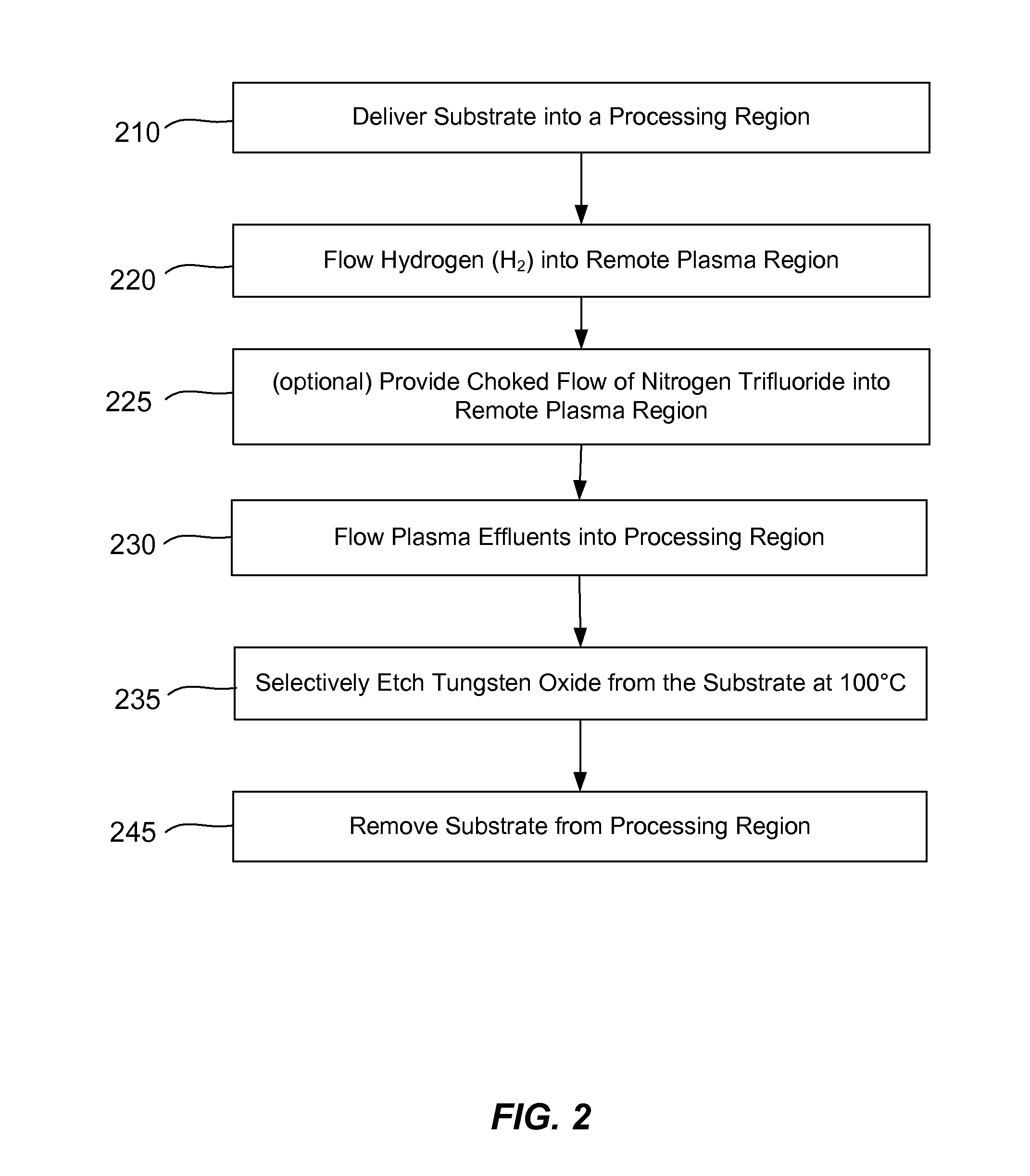
[0027]In order to further appreciate the invention, reference is now made to FIG. 2 which is another but distinct flow chart of a tungsten oxide selective etch process according to disclosed embodiments. The various traits and process parameters discussed with reference to FIG. 1 will not be repeated here except when they deviate from those traits and process parameters. Prior to the first operation, tungsten oxide is formed on a substrate. The substrate is then delivered into a processing region (operation 210). In another embodiment, the tungsten oxide may be formed after delivering the substrate to the processing region, for example, by treating exposed regions of tungsten to a reactive oxygen source.

[0028]A flow of hydrogen (H2) is introduced into a plasma region separate from the processing region (operation 220). The separate plasma region may be referred to as a remote plasma region herein and may be within a distinct module from the processing chamber or a co...


PUM

PropertyMeasurementUnit
temperatureaaaaaaaaaa
pressureaaaaaaaaaa

Abstract

Methods of selectively etching tungsten oxide relative to tungsten, silicon oxide, silicon nitride and / or titanium nitride are described. The methods include a remote plasma etch formed from a fluorine-containing precursor and / or hydrogen (H2). Plasma effluents from the remote plasma are flowed into a substrate processing region where the plasma effluents react with the tungsten oxide. The plasmas effluents react with exposed surfaces and selectively remove tungsten oxide while very slowly removing other exposed materials. In some embodiments, the tungsten oxide selectivity results partly from the presence of an ion suppression element positioned between the remote plasma and the substrate processing region. The ion suppression element reduces or substantially eliminates the number of ionically-charged species that reach the substrate.

Description

CROSS-REFERENCES TO RELATED APPLICATIONS[0001]This application claims the benefit of U.S. Provisional Application No. 61 / 753,677 by Wang et al, filed Jan. 17, 2013, and titled “DRY-ETCH FOR SELECTIVE TUNGSTEN REMOVAL.” This application also claims the benefit of U.S. Provisional Application No. 61 / 732,074 by Kim et al, filed Nov. 30, 2012 and titled “DRY-ETCH FOR SELECTIVE OXIDATION REMOVAL.” Each of the above U.S. Provisional Applications is incorporated herein in its entirety for all purposes.BACKGROUND OF THE INVENTION[0002]Integrated circuits are made possible by processes which produce intricately patterned material layers on substrate surfaces. Producing patterned material on a substrate requires controlled methods for removal of exposed material. Chemical etching is used for a variety of purposes including transferring a pattern in photoresist into underlying layers, thinning layers or thinning lateral dimensions of features already present on the surface. Often it is desirab...

Claims


Application Information

Patent Timeline
Patent Type & Authority Patents(United States)
IPC IPC(8): B44C1/22H01L21/02H01J37/32H01L21/311
CPCH01L21/31122H01L21/02068H01J37/32357H01J2237/334C23C16/0245H01L21/02046H01L21/3065H01L21/31116H01L21/32135H01L21/32136H01L21/76814
Inventor KIM, SANG HYUKYANG, DONGQINGLEE, YOUNG S.JUNG, WEON YOUNGKIM, SANG-JINHSU, CHING-MEIWANG, ANCHUANINGLE, NITIN K.
Owner APPLIED MATERIALS INC
Why Eureka
Try Eureka