Vacuum pump systems for prosthetic limbs and methods of using the same

a technology of vacuum pump and prosthetic limb, which is applied in the field of suspension systems for prosthetic devices, can solve the problems of wasting time, affecting the operation efficiency of the pump system, and the inability of mechanically activated pumps to provide initial air evacuation without effort, etc., and achieves the effect of improving the performance improving the efficiency of the pump system, and improving the size optimization

Active Publication Date: 2015-06-30
U S GOVERNMENT REPRESENTED BY THE DEPT OF VETERANS AFFAIRS +1
View PDF25 Cites 20 Cited by
  • Summary
  • Abstract
  • Description
  • Claims
  • Application Information

AI Technical Summary

Benefits of technology

[0016]To further enhance the performance of pump systems for suspension of a prosthetic limb, the present disclosure also provides pump systems that include an electrically activated pump, such as of the micro pump type utilized in exclusively electrical systems, thereby providing a modular hybrid system. A hybrid pump system may offer significant advantages, such as the desired rapid engagement upon initial donning of the prosthetic device, while not requiring solely battery power to evacuate air and to maintain appropriate vacuum levels. This may permit elongated intervals between charging of rechargeable batteries or battery packs, or between replacement of disposable batteries. A hybrid system also may provide for better optimization of the size and capacities of the components utilized, as the mechanically activated pump portion of a hybrid system need not be as concerned with the ability to rapidly establish initial evacuation solely via the mechanically activated pump, while the electrically activated pump is less likely to be cycled during the course of many activities that now will provide operation of a mechanically activated pump. Accordingly, depending on the length of the residual limb, it may be possible to implement a hybrid pump system of this disclosure within a system having a relatively short length, such that it could be located above the knee joint for a transfemoral amputee.
[0017]Thus, a hybrid system may utilize the respective strengths of mechanically and electrically activated pumps to achieve superior overall performance, while essentially also providing a redundant pump system to ensure at least adequate performance for the user. By utilizing a low profile design, the systems also permit placement above the knee for a transfemoral amputee, for direct interaction with a socket of a prosthetic device. The pump systems preferably have a height of about 1.5 inches or less, to permit positioning above the knee. It will be appreciated that the height may be more or less, depending on the configuration of mechanically activated pump, and whether or not the system includes an electrically activated pump, as well as its configuration. This, in turn, helps avoid many of the hindrances associated with below knee systems, while permitting an inline assembly that need not require external tubing.

Problems solved by technology

Electrically activated pumps also may generate undesirable noise.
However, the mechanically activated pumps do not provide initial evacuation of air without effort, take longer to achieve operative vacuum levels, and typically need periodic motion to maintain appropriate vacuum levels.
Mechanically activated pumps also tend to require a significant length for operation, as they typically operate by using a telescoping assembly.
Mechanically activated pumps generally are configured for mounting below the knee because the pumps are too long to fit between the socket and the knee joint of the prosthetic limb, and as such, are not as well suited for transfemoral amputees.
An active soldier with amputation may be in the field for a prolonged period of time, with a need to maintain proper vacuum levels for suspension, while being without access to a power source for recharging of batteries.

Method used


Image

  • Vacuum pump systems for prosthetic limbs and methods of using the same
  • Vacuum pump systems for prosthetic limbs and methods of using the same
  • Vacuum pump systems for prosthetic limbs and methods of using the same

Examples


Embodiment Construction

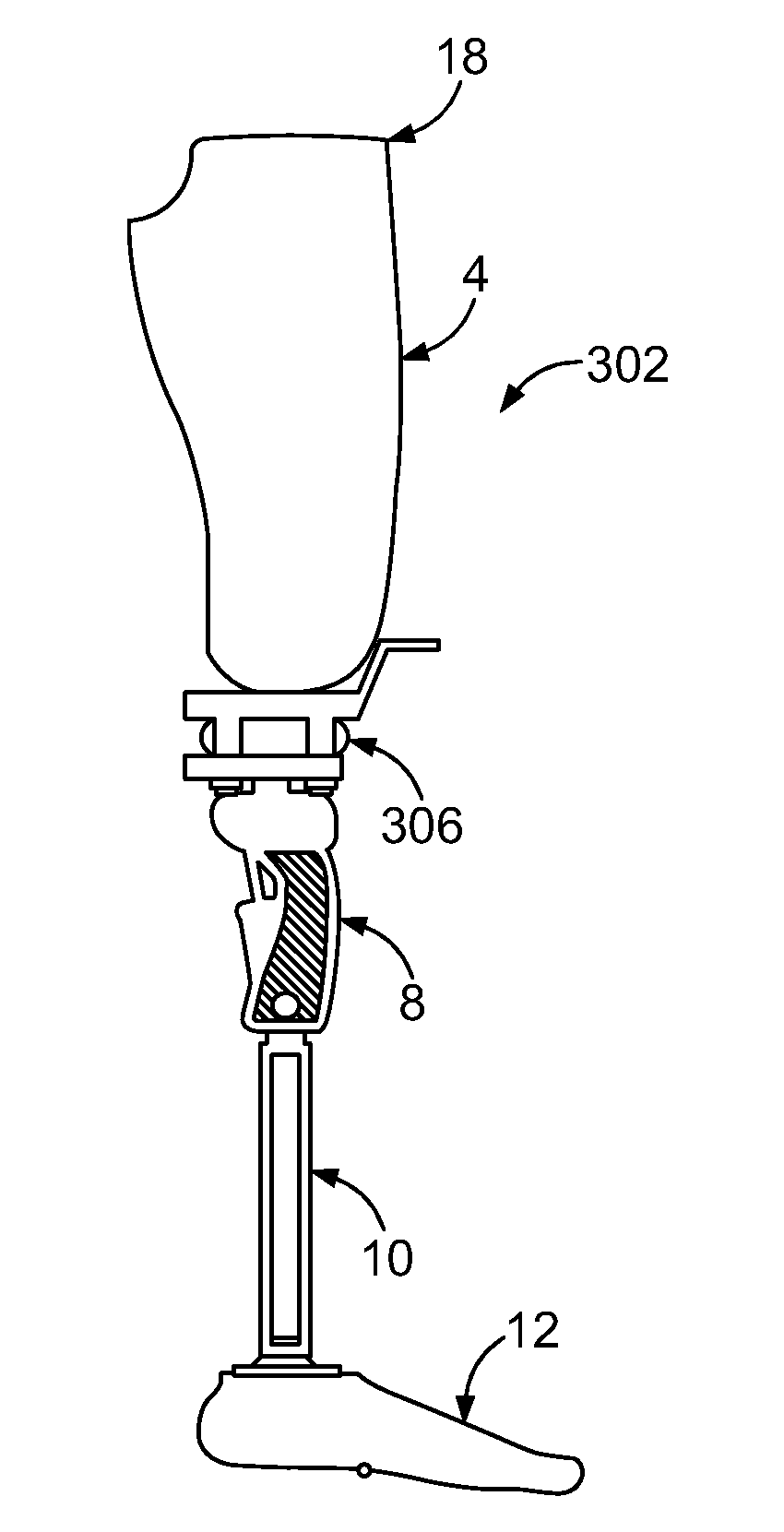
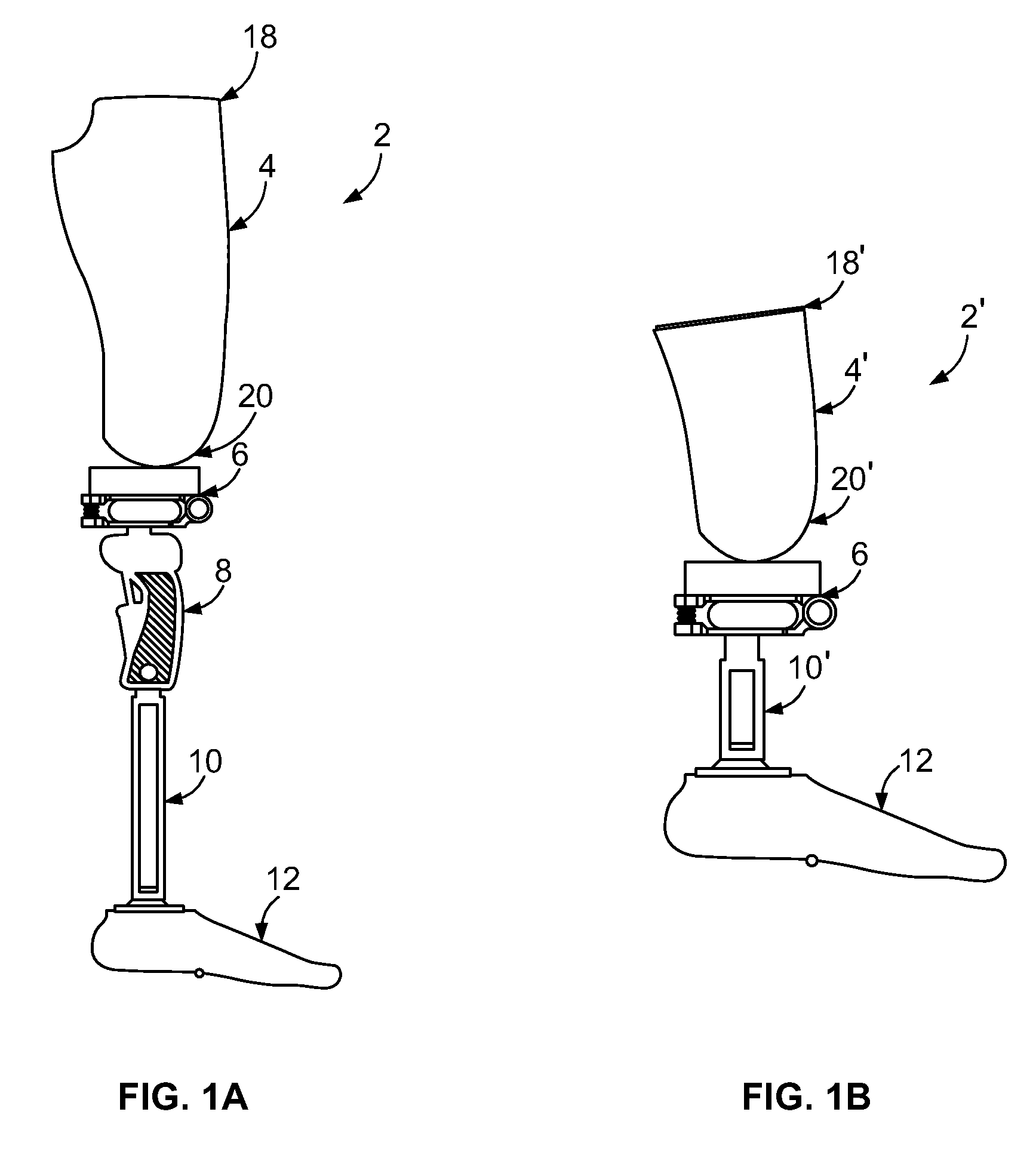
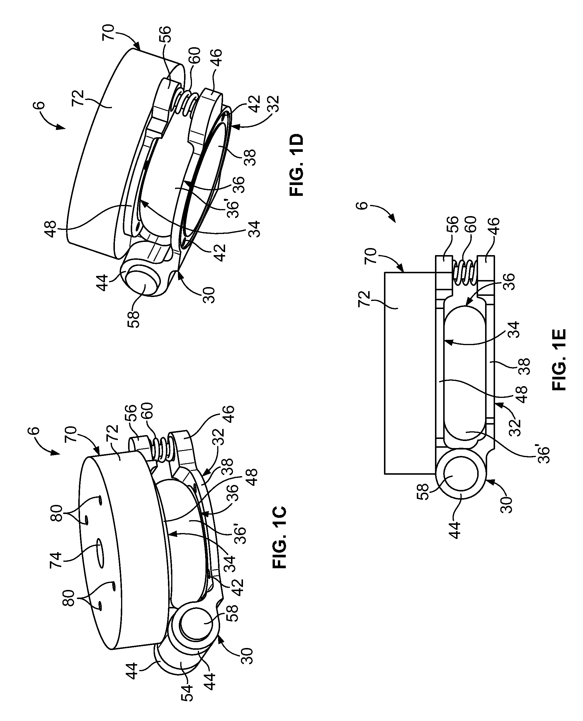
[0061]Referring generally to FIGS. 1A-4H, it will be appreciated that a vacuum pump system for use in suspension of a prosthetic device from a residual limb of the present disclosure generally may be embodied within numerous configurations of pump systems having a mechanically activated pump and / or a hybrid pump system having a mechanically activated pump and an electrically activated pump. Indeed, while acknowledging that all of the example configurations may include at least one of the example mechanically activated pumps, it is contemplated that a pump system may be incorporated into various prosthetic devices, such as transfemoral and transtibial prosthetic limbs.

[0062]FIG. 1A shows a simplified side view of a prosthetic device or limb 2 in the form of a prosthetic limb for a transfemoral amputee. The prosthetic device 2 generally includes a socket 4, a first example pump system 6, a knee joint 8, a pylon 10 and a prosthetic foot 12. The socket 4 has an upper end 18 that is open...


PUM


Abstract

Pump systems for use in suspension of a prosthetic device from a residual limb and methods of suspending a prosthetic device from a residual limb are disclosed. The pump systems include a mechanically activated pump having a first compression member coupled to a second compression member, a compressible bladder disposed between the first and second compression members, and coupling elements that engage and couple together the first and second compression members. The mechanically activated pump may be connected with an electrically activated pump within a fluid circuit of a hybrid pump system to provide vacuum engagement between a prosthetic device and a residual limb.

Description

CROSS-REFERENCE TO RELATED APPLICATION[0001]This application claims the benefit of U.S. Provisional Patent Application Ser. No. 61 / 571,233, filed Jun. 23, 2011, the disclosure of which is hereby incorporated by reference in its entirety.CONTRACTUAL ORIGIN OF THE INVENTION[0002]This invention was made with government support under Grant No. W81XWH-10-1-0744 awarded by the U.S. Army Medical Research and Material Command. The government has certain rights in the invention.BACKGROUND OF THE INVENTION[0003]1. Field of the Invention[0004]The present invention generally relates to suspension systems for prosthetic devices, and more particularly to vacuum pump systems for prosthetic limbs that include at least a mechanically activated pump.[0005]2. Discussion of the Prior Art[0006]Various systems have been developed for coupling a prosthetic device or prosthetic limb to a residual limb. The residual limb is connected to the prosthesis via a socket which receives and holds in place an end po...

Claims


Application Information

Patent Timeline
Patent Type & Authority Patents(United States)
IPC IPC(8): A61F2/80A61F2/68A61F2/60A61F2/70A61F2/74A61F2/76A61F2/50
CPCA61F2/80A61F2/68A61F2002/501A61F2002/5073A61F2002/608A61F2002/689A61F2002/704A61F2002/741A61F2002/742A61F2002/7655A61F2002/802A61F2002/6809A61F2/60A61F2/70A61F2/741A61F2/742A61F2002/607A61F2/74
Inventor CALDWELL, RYAN J.HANSEN, ANDREW H.WOOD, SEAN M.CHEN, WEIRADCLIFFE, REGAN A.YNGVE, KEVIN A.KUHAR, BENNETT E.NELSON, ANDREW J.NICKEL, ERIC
Owner U S GOVERNMENT REPRESENTED BY THE DEPT OF VETERANS AFFAIRS
Why Eureka
Try Eureka