Apparatus for manufacturing thermoelectric conversion element

a technology of thermoelectric conversion element and manufacturing method, which is applied in the manufacture/treatment of thermoelectric devices, furnaces, charge manipulation, etc., can solve the problem of extremely small yield and achieve the effect of high connection reliability and high density array

Active Publication Date: 2015-07-21
PANASONIC INTELLECTUAL PROPERTY MANAGEMENT CO LTD
View PDF40 Cites 0 Cited by
  • Summary
  • Abstract
  • Description
  • Claims
  • Application Information

AI Technical Summary

Benefits of technology

[0033]The present invention can realize an apparatus and a method for manufacturing a thermoelectric conversion element facilitating a high-density array and offering high connection reliability.

Problems solved by technology

Crystal materials generally used as thermoelectric conversion elements are Bi2Te3-based materials and these crystals have an outstanding cleavage property and these crystals are known to have a problem that after undergoing slicing and dicing steps or the like to obtain a thermoelectric conversion element from an ingot, the yield becomes extremely small due to cracking or chipping.

Method used


Image

  • Apparatus for manufacturing thermoelectric conversion element
  • Apparatus for manufacturing thermoelectric conversion element
  • Apparatus for manufacturing thermoelectric conversion element

Examples


embodiment 1

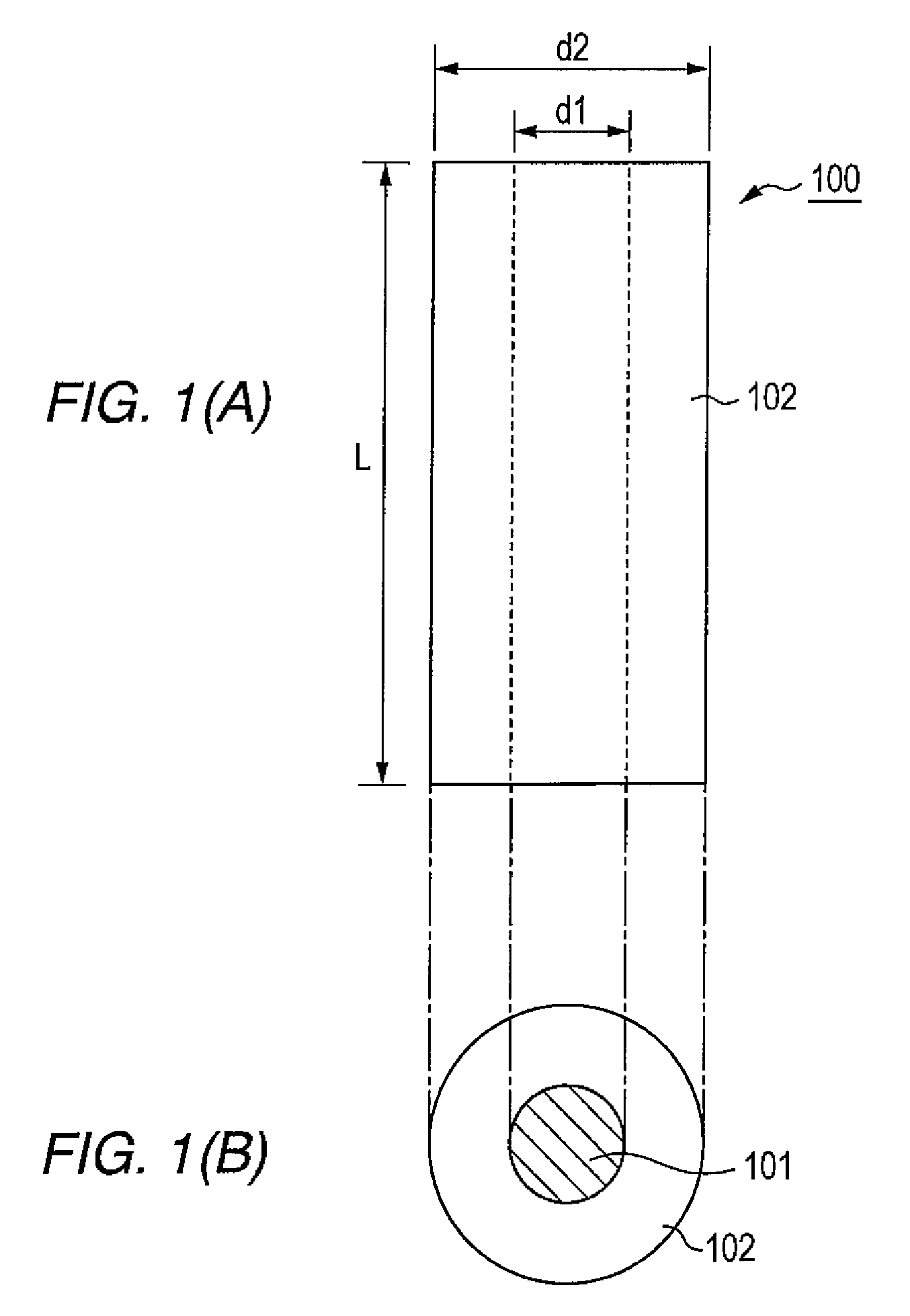
[0062]FIG. 1(A) and FIG. 1(B) illustrate thermoelectric conversion element 100 according to Embodiment 1 of the present invention. FIG. 1(A) is a side view of thermoelectric conversion element 100 and FIG. 1(B) is a bottom view of thermoelectric conversion element 100. In FIG. 1(A) and FIG. 1(B), reference numeral 101 denotes a thermoelectric conversion material. 102 denotes a tube made of heat-resisting insulating material. Thermoelectric conversion material 101 is in close contact with the inner perimeter surface of tube 102 filling the interior of tube 102. For example, overall length L of thermoelectric conversion element 100 is about 1.3 to about 3.0 mm, inner diameter d1 of tube 102 is about 1.8 mm and outer diameter d2 of tube 102 is about 3.0 mm.

[0063]Thermoelectric conversion material 101 is a material that produces an electromotive force when a temperature difference is produced between both ends thereof. Thermoelectric conversion material 101 may be selected according to ...

embodiment 2

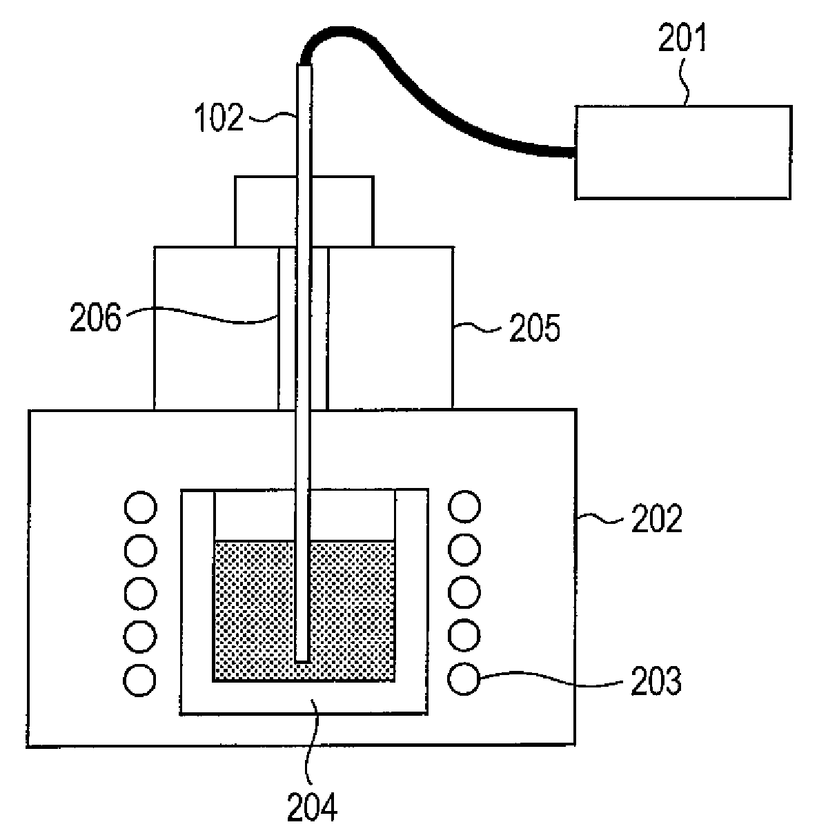
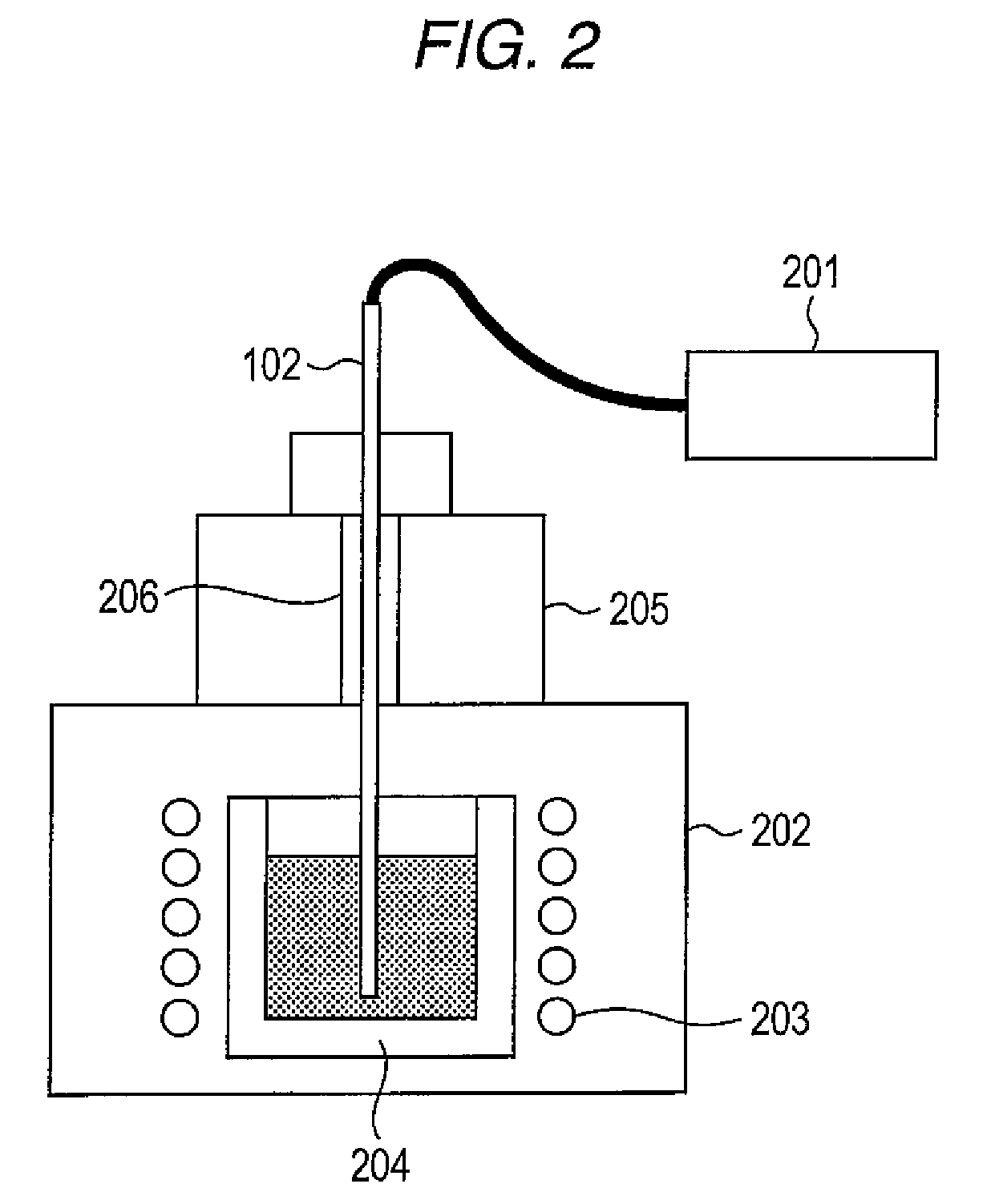
[0088]FIG. 5 is a diagram schematically illustrating a configuration of a second example of the apparatus 12 for manufacturing a thermoelectric conversion element of the present invention. The manufacturing apparatus 12 of the present embodiment is the same as the manufacturing apparatus according to Embodiment 1, instead of tube 103 decompression degree adjusting apparatus 500 is provided.

[0089]Decompression degree adjusting apparatus 500 includes buffer chamber 501, pressure gauge 502 (also denoted by “Y”) that detects a pressure of buffer chamber 501, two nozzles 503 and 504, valves 505 and 506 that open / close nozzles 503 and 504, and piston 507. Buffer chamber 501 is, for example, a hollow column body. Pressure gauge 502 is arranged on one end face of the column body. Pressure gauge 502 is a differential pressure gauge that detects a pressure lower than an atmospheric pressure as a pressure difference. Nozzles 503 and 504 are arranged on the circumferential surface of the column...

embodiment 3

[0093]FIG. 6(A) is a diagram schematically illustrating a configuration of a third example of an apparatus 13 for manufacturing a thermoelectric conversion element of the present invention. FIG. 6(B) is an enlarged view of main parts in FIG. 6(A) (periphery of inner cover 600). The manufacturing apparatus of the present embodiment is the same as the manufacturing apparatus according to Embodiment 1 except that inner cover 600 is further provided.

[0094]Inner cover 600 is a carbon disk. The outer diameter of inner cover 600 is slightly smaller than the inner diameter of crucible 204. Inner cover 600 includes through-hole 601 in the center. The hole diameter of through-hole 601 is slightly larger than the outer diameter of tube 102.

[0095]The method for manufacturing a thermoelectric conversion element using the manufacturing method of the present embodiment is the same as that of Embodiment 1 except that inner cover 600 is arranged on the thermoelectric conversion material in crucible ...


PUM


Abstract

The present invention relates to an apparatus and a method for manufacturing a thermoelectric conversion element. The present invention provides an apparatus for manufacturing a thermoelectric conversion element that can easily realize a high-density array of thermoelectric conversion elements and secure connection reliability. This is an apparatus for manufacturing a thermoelectric conversion element that sucks a p-type or n-type thermoelectric conversion material into heat-resisting insulating tube 102 and includes preheating apparatus 205 that can heat tube 102 to a predetermined temperature before sucking the melted thermoelectric conversion element. Tube 102 whose temperature condition is adjusted by being heated by preheating apparatus 205 is inserted into crucible 204 and the molten thermoelectric conversion material is sucked into tube 102 by decompression apparatus 201.

Description

TECHNICAL FIELD[0001]The present invention relates to a method and an apparatus for manufacturing a thermoelectric conversion element.BACKGROUND ART[0002]Elements taking advantage of a Peltier effect or Seebeck effect are used as thermoelectric conversion elements. Since thermoelectric conversion elements have a simple structure, are easy to handle and able to maintain a stable characteristic, widespread use of thermoelectric conversion elements is attracting attention in recent years. Especially when used as an electronic cooling element, the thermoelectric conversion element can perform local cooling and accurate control over temperature close to a room temperature, and therefore a wide range of studies are being carried forward aiming at temperature stabilization of opto-electronics and semiconductor laser or the like.[0003]The aforementioned electronic cooling element or thermoelectric module used for thermoelectric power generation is configured as shown in FIG. 7 by connecting...

Claims


Application Information

Patent Timeline
Patent Type & Authority Patents(United States)
IPC IPC(8): H01L35/34F27D3/14
CPCH01L35/34F27D3/14H10N10/01
Inventor HIGASHIDA, TAKAAKIKUBO, TAKASHITOYODA, KAORIMAESHIMA, SATOSHI
Owner PANASONIC INTELLECTUAL PROPERTY MANAGEMENT CO LTD
Why Eureka
Try Eureka