
Ink-jet recording head, manufacturing method of the same and ink-jet recording apparatus

a manufacturing method and recording head technology, applied in the field of inkjet recording head, can solve the problems of inability to achieve difficult high-density array of piezoelectric elements, and sometimes slippage of light exposure, and achieve the effect of simplifying the manufacturing process of ink-jet recording head and high accuracy

Inactive Publication Date: 2006-11-14
SEIKO EPSON CORP
View PDF22 Cites 3 Cited by
  • Summary
  • Abstract
  • Description
  • Claims
  • Application Information

AI Technical Summary

Benefits of technology

The present invention provides an ink-jet recording head with improved ink ejection characteristics and stability. The invention also allows for the high-density arrangement of pressure generating chambers and reduces cross talk between them. The invention includes a passage-forming substrate with a pressure generating chamber formed thereon, a piezoelectric element formed of a thin film and vibration plate, and a reinforcement layer. The invention also provides a manufacturing method and an ink-jet recording apparatus using the ink-jet recording head. The technical effects of the invention include improved accuracy of the position of the piezoelectric element and pressure generating chamber, increased rigidity of the pressure generating chamber, reduced cross talk between pressure generating chambers, and improved ink ejection characteristics.

Problems solved by technology

On the contrary, a difficult process in which the piezoelectric element is cut and divided in a comb teeth shape to make it coincide with the array pitch of the nozzle orifice and a method so that the cut and divided piezoelectric element is aligned and fixed to the pressure generating chamber is necessary, thus there is a problem of a complex manufacturing process.
However, a certain size of vibration plate is required due to the usage of flexural vibration, thus there is a problem that high density array of the piezoelectric elements is difficult.
However, in such an ink-jet recording head, an error sometimes occurs in aligning the mask pattern for forming the piezoelectric element and the mask pattern for forming the pressure generating chamber, alternatively slippage of light exposure sometimes occurs due to a warp or the like of the plate where the pressure generating chamber is formed.
Therefore, there is a problem that the relative positional accuracy between the piezoelectric element and the pressure generating chamber is lowered.
Therefore, the relative positional accuracy between the piezoelectric element and the pressure generating chamber is lowered, thus causing problems of low ink ejection characteristics and low stability thereof.
Furthermore, in the case where the pressure generating chambers are arrayed in a high density, the thickness of compartment walls between the pressure generating chambers is made thin which results in lack of rigidity of the compartment walls, thus causing the problem that cross talk occurs among the pressure generating chambers.
However, in this case, an operation such as processing and pasting for the wide width portion of the pressure generating chamber is required, thus causing problems on operationality and accuracy.

Method used


Image

  • Ink-jet recording head, manufacturing method of the same and ink-jet recording apparatus
  • Ink-jet recording head, manufacturing method of the same and ink-jet recording apparatus
  • Ink-jet recording head, manufacturing method of the same and ink-jet recording apparatus

Examples


embodiment 1

(Embodiment 1)

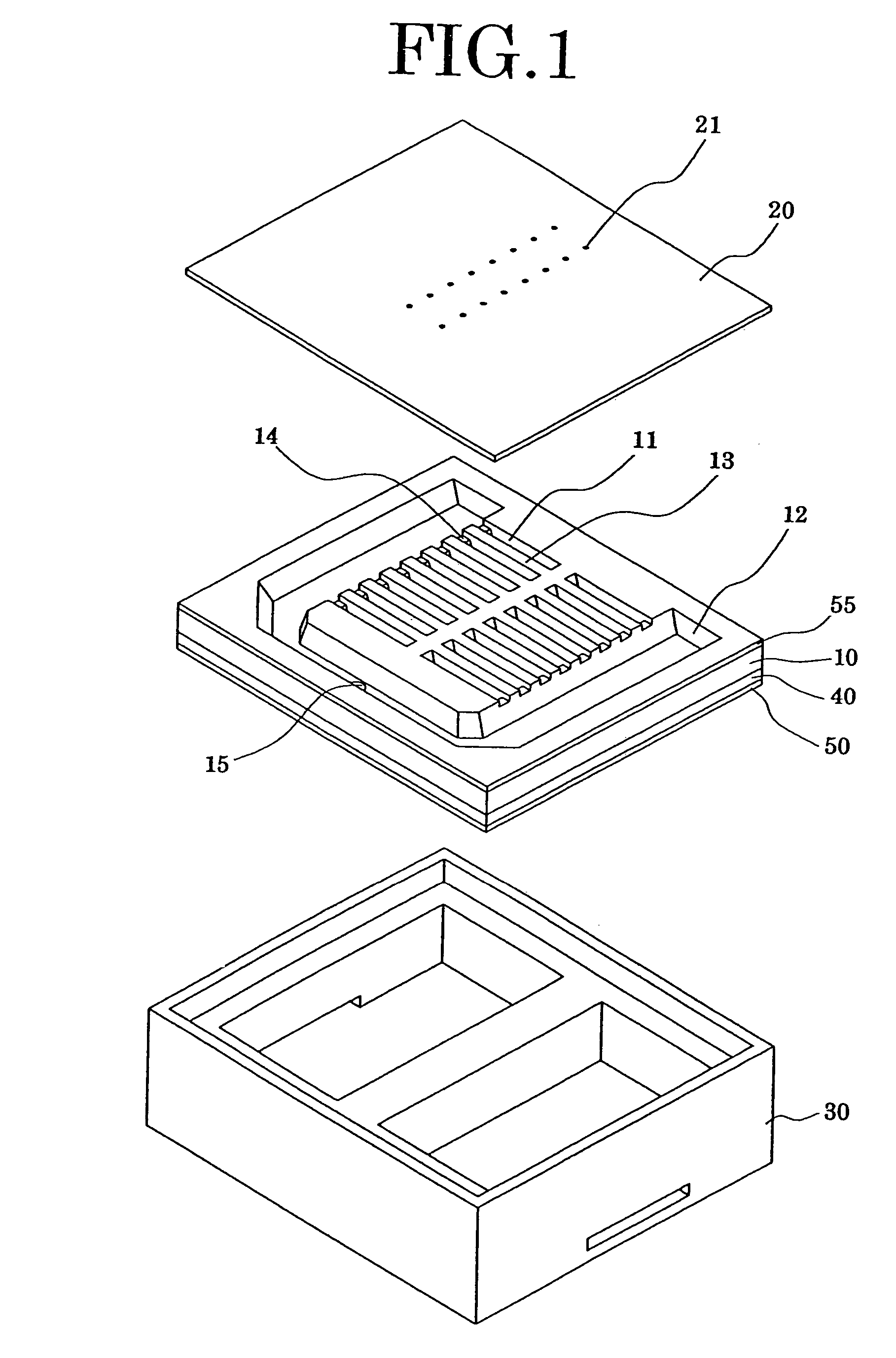
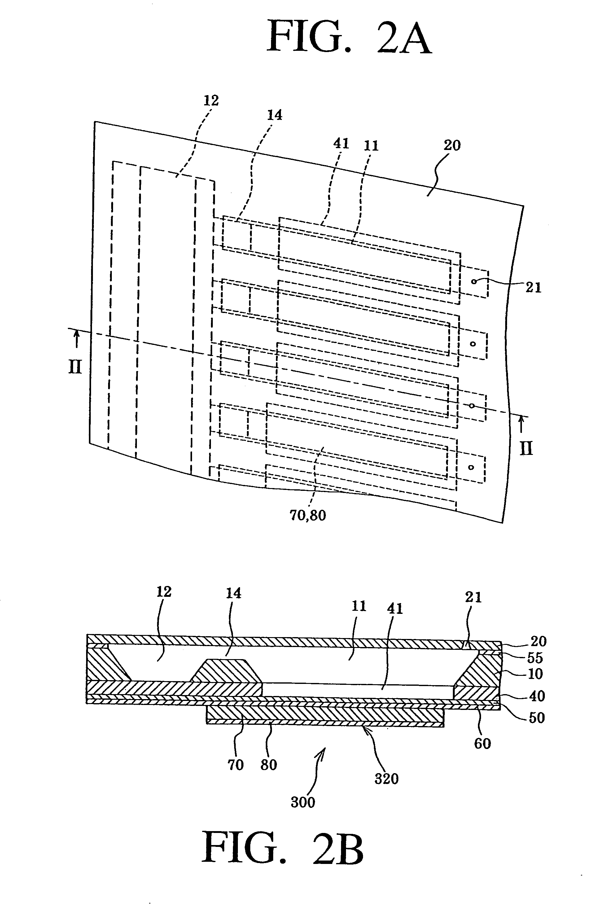
[0075]FIG. 1 is an exploded perspective view showing the ink-jet recording head according to embodiment 1 of the present invention. FIG. 2(a) is a plan view showing principal portions of the ink-jet recording head, and FIG. 2(b) is a view showing a cross-sectional structure of the pressure generating chamber as one of the principal portions along the longitudinal direction.

[0076]As shown in the drawings, a passage-forming substrate 10 consists of a single crystal silicon substrate having a plane (110) of the plane orientation in this embodiment. As the passage-forming substrate 10, a plate having a thickness of about 150 to 300 μm is typically used, and a plate desirably having a thickness of about 180 to 280 μm, more desirably, about 220 μm is preferable. This is because array density can be increased while maintaining the rigidity of the compartment walls between the pressure generating chambers adjacent from one to another.

[0077]In the passage-forming substrate 10, ...

embodiment 2

(Embodiment 2)

[0107]FIGS. 7(a) and 7(b) are respectively a plan view and a cross-sectional view showing principal portions of the ink-jet recording head according to embodiment 2.

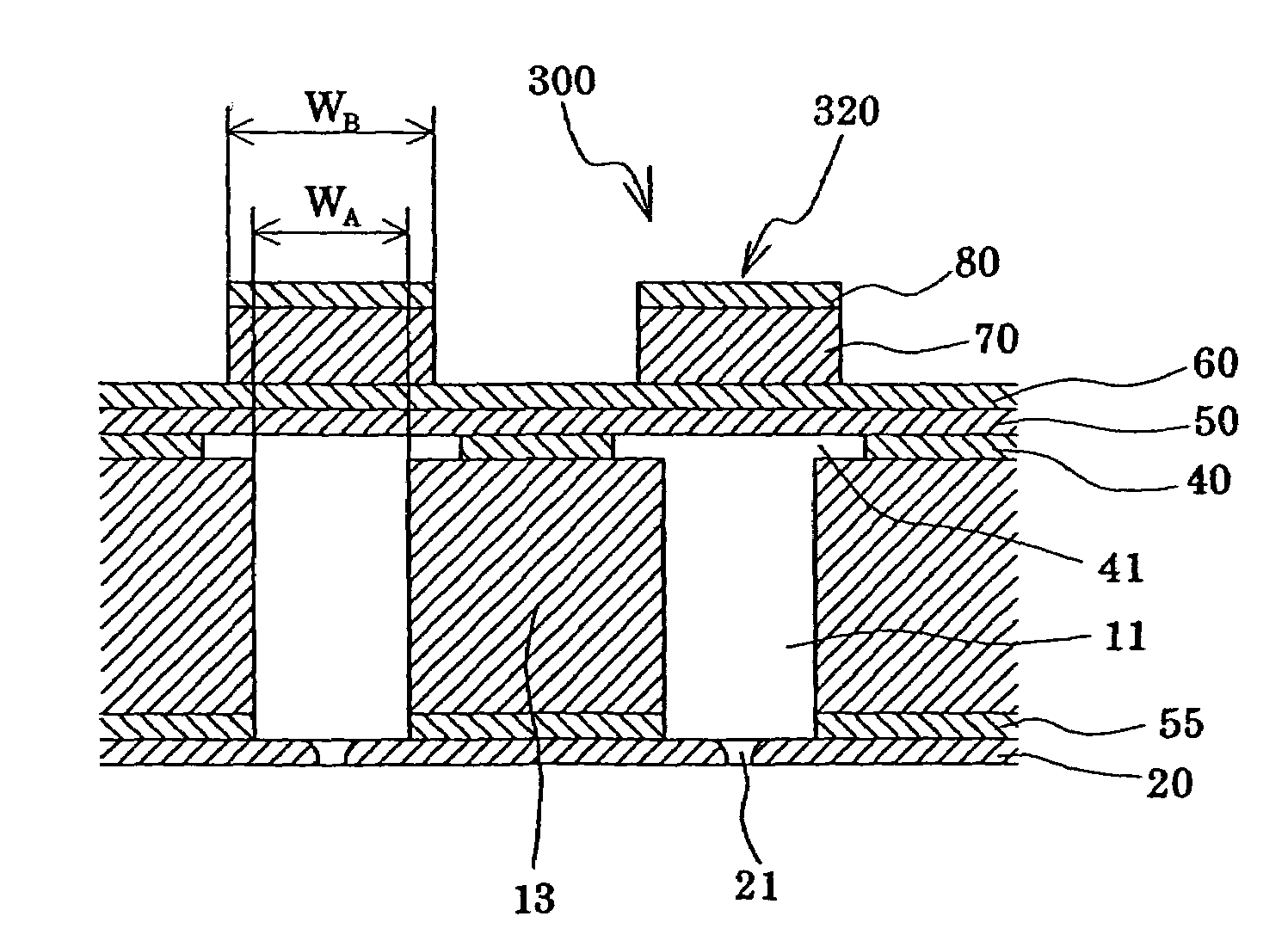
[0108]As shown in FIGS. 7(a) and 7(b), the present embodiment is an example where the width of the pressure generating chamber 11 is made equal to the diameter of the nozzle orifice 21 or less. The present embodiment is similar to embodiment 1 except that a nozzle expansion portion 16 having a width wider than the diameter of the nozzle orifice 21 and wider than the width of the pressure generating chamber 11 is provided in the communicating portion between the pressure generating chamber 11 and the nozzle orifice 21.

[0109]Herein, the relation between the width of the pressure generating chamber 11 and the diameter of the nozzle orifice 21 is not specifically limited. However, in the case where the width WA of the pressure generating chamber 11 is equal to the diameter of the nozzle orifice 21 or less as in...

embodiment 3

(Embodiment 3)

[0112]FIGS. 8(a) and 8(b) are respectively a plan view and a cross-sectional view showing principal portions of the ink-jet recording head according to embodiment 3.

[0113]As shown in FIGS. 8(a) and 8(b), the present embodiment is similar to embodiment 1 except that a step difference portion extending opposite to the passage-forming substrate 10 is provided in the elastic film 50 in the region corresponding to the pressure generating chamber and a space portion 41A is defined by the step difference portion and the passage-forming substrate.

[0114]Note that, in the case where the space portion 41A substantially constitutes a portion of the pressure generating chamber 11, the height of the space portion 41A, that is, the height of the step difference portion 50a of the elastic film 50, is preferably set to be in the range of 0.1 μm to 100 μm, more preferably, 1 μm to 10 μm.

[0115]Also with such a constitution of the present embodiment, since the vibration region of the vibr...


PUM

PropertyMeasurementUnit
heightaaaaaaaaaa
heightaaaaaaaaaa
thicknessaaaaaaaaaa

Abstract

A manufacturing method of an ink-jet recording head for improving relative positional accuracy between a piezoelectric element and a pressure generating chamber to improve ink ejection characteristics and stability thereof. The manufacturing method includes the steps of: forming a passage-forming layer on a passage-forming substrate and imparting etching selectivity to a region that will be a space portion of the passage-forming layer; forming a vibration plate on the passage-forming layer and a piezoelectric element; performing anisotropic etching on the passage-forming substrate to form a penetrated portion at least to a region that will be the space portion, etching the passage-forming layer to form the space portion, and forming a pressure generating chamber opposite the space portion; and joining a nozzle plate to the passage-forming substrate.

Description

[0001]This is a divisional of application Ser. No. 09 / 756,292 filed Jan. 9, 2001, and now U.S. Pat. No. 6,712,456, the disclosure of which is incorporated herein by reference.BACKGROUND OF THE INVENTION[0002]The present invention relates to an ink-jet recording head, in which a piezoelectric element is formed via a vibration plate in a portion of a pressure generating chamber communicating with a nozzle orifice that ejects ink droplets, and ink droplets are ejected by displacement of the piezoelectric element. Furthermore, the present invention relates to a manufacturing method of the same and an ink-jet recording apparatus.[0003]Two types of recording heads are put into practical use with regard to the ink-jet recording head, in which a portion of a pressure generating chamber communicating with a nozzle orifice that ejects ink droplets is constituted of a vibration plate, and the vibration plate is deformed by a piezoelectric element to pressurize ink in the pressure generating ch...

Claims


Application Information

Patent Timeline
Patent Type & Authority Patents(United States)
IPC IPC(8): B41J2/04H01L21/00B41J2/045B41J2/055B41J2/14B41J2/16
CPCB41J2/14233B41J2/161B41J2/1623B41J2/1629B41J2/1632B41J2/1639B41J2/1646B41J2/1631Y10T29/49401B41J2002/14419
Inventor MATSUZAWA, AKIRASHIMADA, MASATOTAKAHASHI, TETSUSHI
Owner SEIKO EPSON CORP
Learn More