High-voltage power supply module and power supply system

a high-voltage power supply and power supply system technology, applied in emergency power supply arrangements, instruments, process and machine control, etc., can solve the problems of increasing the volume of the power supply b>1/b>, reducing the number of selective components, and increasing the overall volume of the power supply. , to achieve the effect of reducing the safety distance of the power supply module, reducing the volume of the high-voltage power supply module, and reducing the cost of fabrication

Inactive Publication Date: 2015-07-21
DELTA ELECTRONICS INC
View PDF11 Cites 2 Cited by
  • Summary
  • Abstract
  • Description
  • Claims
  • Application Information

AI Technical Summary

Benefits of technology

[0007]The present invention provides high-voltage power supply module and a power supply system with such a high-voltage power supply module. The output sides of the first isolation converter and the second isolation converter are serially connected with a connecting terminal, and then connected with a ground terminal. Consequently, the voltage of the output positive terminal of the first isolation converter with respect to the ground terminal or the voltage of the output negative terminal of the second isolation converter with respect to the ground terminal is reduced. In such way, the demands on the safety regulation and the safety distance of the power supply module will be reduced. Moreover, since the number of the selective components of the high-voltage power supply module is increased, the fabricating cost and the volume of the high-voltage power supply module will be reduced.

Problems solved by technology

Under this circumstance, the number of selective components is reduced, and the fabricating cost is increased.
Moreover, since the volume of the common high-voltage resistant component is relatively bulky, the overall volume of the power supply 1 is increased.

Method used


Image

  • High-voltage power supply module and power supply system
  • High-voltage power supply module and power supply system
  • High-voltage power supply module and power supply system

Examples


Embodiment Construction

[0018]The present invention will now be described more specifically with reference to the following embodiments. It is to be noted that the following descriptions of preferred embodiments of this invention are presented herein for purpose of illustration and description only. It is not intended to be exhaustive or to be limited to the precise form disclosed.

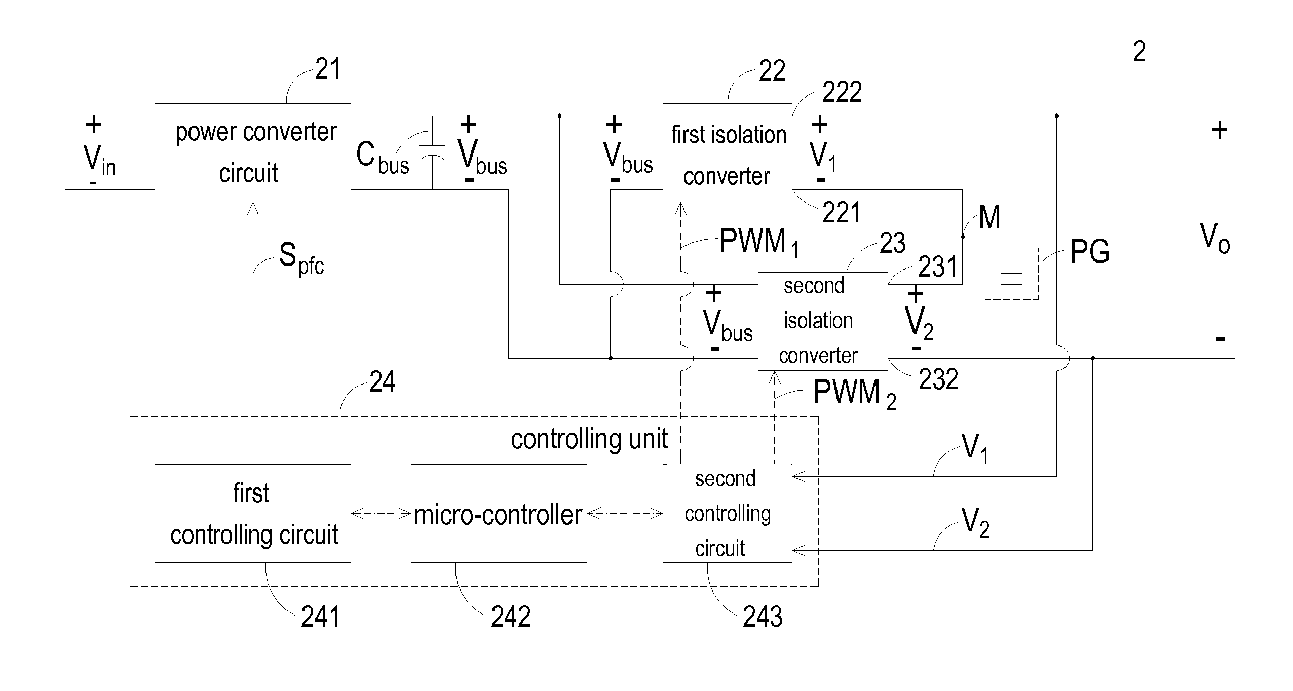
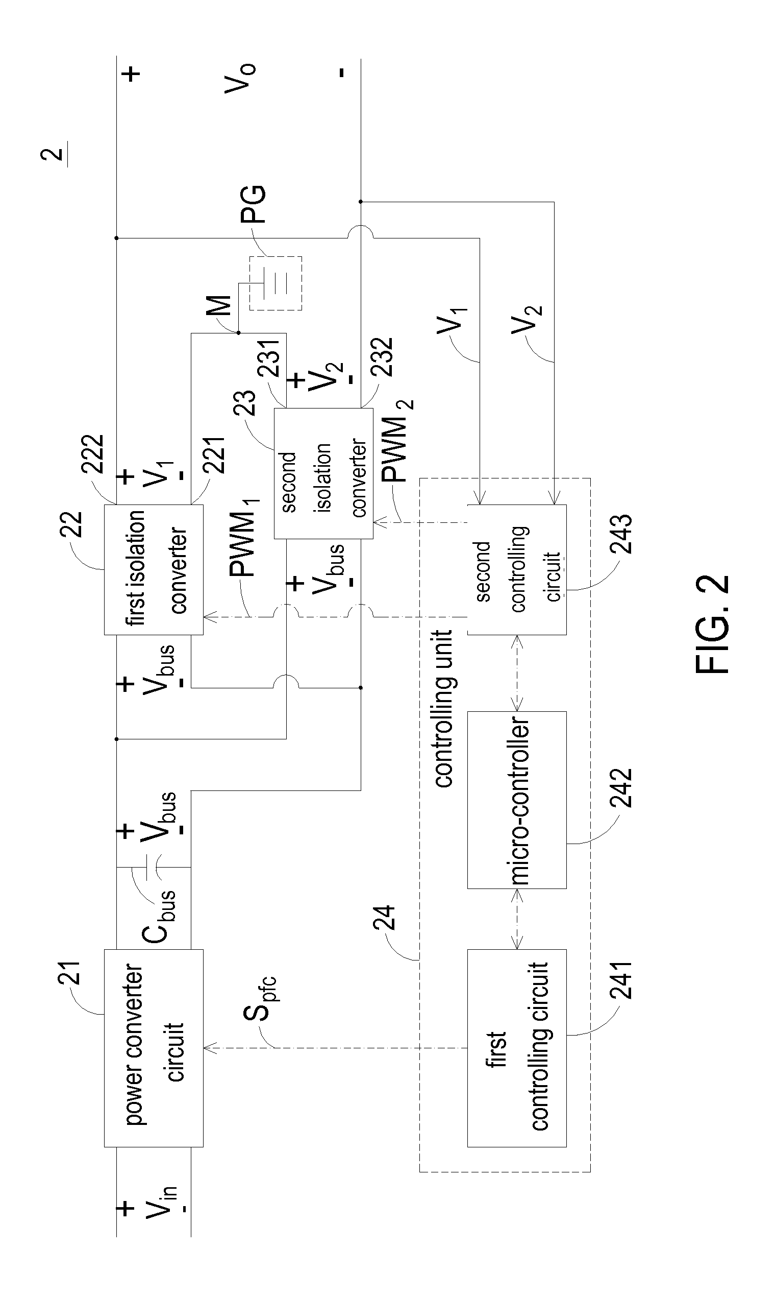
[0019]FIG. 2 is a schematic circuit block diagram illustrating a high-voltage power supply module according to an embodiment of the present invention. As shown in FIG. 2, the high-voltage power supply module 2 comprises a power converter circuit 21, a first isolation converter 22, a second isolation converter 23, a ground terminal PG and a controlling unit 24. By the power converter circuit 21, an input voltage Vin is converted into a bus voltage Vbus. By the first isolation converter 22, the bus voltage Vbus is converted into a first voltage V1. The first isolation converter 22 comprises a first output negative terminal 221 and ...


PUM


Abstract

A high-voltage power supply module includes a front-end power converting circuit, a first back-end circuit, a second back-end circuit, a ground terminal and a controlling unit. The front-end power converting circuit receives an input voltage and converts the input voltage into a bus voltage. The first back-end circuit receives the bus voltage and outputs a first voltage. The second back-end circuit receives the bus voltage and outputs a second voltage. The first back-end circuit and the second back-end circuit are connected with a connecting terminal. The ground terminal is connected with the connecting terminal. In response to the first voltage and the second voltage, a first control signal and a second control signal are respectively issued from the controlling unit to the first back-end circuit and the second back-end circuit, thereby adjusting the magnitudes of the first voltage and the second voltage.

Description

FIELD OF THE INVENTION[0001]The present invention relates to a power supply module, and more particularly to a high-voltage power supply module. The present invention also relates to a power supply system with such a high-voltage power supply module.BACKGROUND OF THE INVENTION[0002]For reducing power loss and increasing efficiency of a power supply, a high-voltage DC power supply system is provided. By the high-voltage power supply system, the process of converting an AC voltage to a DC voltage is omitted before the electricity is transmitted to the load. Consequently, the operating efficiency is enhanced. Moreover, in views of long-distance power distribution, the high-voltage DC power supply system is more cost-effective and has less power loss than the common AC power supply system. Therefore, the trend of designing a high-voltage DC power supply system is toward low power consumption.[0003]Generally, the high-voltage power supply system comprises a power supply. As known, an iso...

Claims


Application Information

Patent Timeline
Patent Type & Authority Patents(United States)
IPC IPC(8): H02J1/00H02M3/335H02M1/00H02J1/10H02J7/34
CPCH02M3/33523H02J1/108H02J7/34H02M2001/0077Y10T307/625H02M1/0077
Inventor LAI, YUAN-FANGCHANG, YING-SUNG
Owner DELTA ELECTRONICS INC
Why Eureka
Try Eureka