Open loop heat pipe radiator having a free-piston for wiping condensed working fluid

a working fluid and open-loop technology, applied in the field of cooling systems, can solve the problems of high cost of lifting payloads to orbit necessitate thermal management systems, production of several times as much unusable power as is converted to electricity, and the limited size of solar cells, etc., to achieve the effect of low mass-to-power ratio, large size and high mass

Inactive Publication Date: 2015-07-28
NASA
View PDF35 Cites 6 Cited by
  • Summary
  • Abstract
  • Description
  • Claims
  • Application Information

AI Technical Summary

Benefits of technology

[0006]The object of the present invention is to overcome the aforementioned drawbacks of relatively high mass and limitations in size and to provide a heat pipe radiator having a low mass-to-power ratio. The present invention is capable of being manufactured to a large size to provide adequate cooling capacity while maintaining the low mass-to-power ratio desired to provide reduced cost of lifting the radiator into space.

Problems solved by technology

Both nuclear and concentrator types of solar space-based sources of electricity result in the production of several times as much unusable power as is converted to electricity.
The high cost of lifting payloads to orbit necessitates thermal management systems with the minimum mass possible.
For example, solar cells are presently limited to operate at a maximum cell temperature below 100° C. If concentrator cells are used, the excess energy is much greater than the amount that can be radiated directly by the cells at these temperatures so an auxiliary radiator is typically needed.
However, wick return or direct pumping of the condensed liquid by the gas within the condenser limits the liquid return rate and the tied up liquid caused by the limited return rate adds to the total mass (and therefore the cost to lift into space) of these systems.
The use of external pump return (open loop) has been previously limited due to the difficulty of isolating and collecting the condensed liquid.

Method used


Image

  • Open loop heat pipe radiator having a free-piston for wiping condensed working fluid
  • Open loop heat pipe radiator having a free-piston for wiping condensed working fluid
  • Open loop heat pipe radiator having a free-piston for wiping condensed working fluid

Examples


Embodiment Construction

[0019]The present invention now will be described more fully hereinafter with reference to the accompanying drawings, in which preferred embodiments of the invention are shown. This invention may, however, be embodied in many different forms and should not be construed as limited to the embodiments set forth herein; rather, these embodiments are provided so that this disclosure will be thorough and complete, and will fully convey the scope of the invention to those skilled in the art. Like numbers refer to like elements throughout.

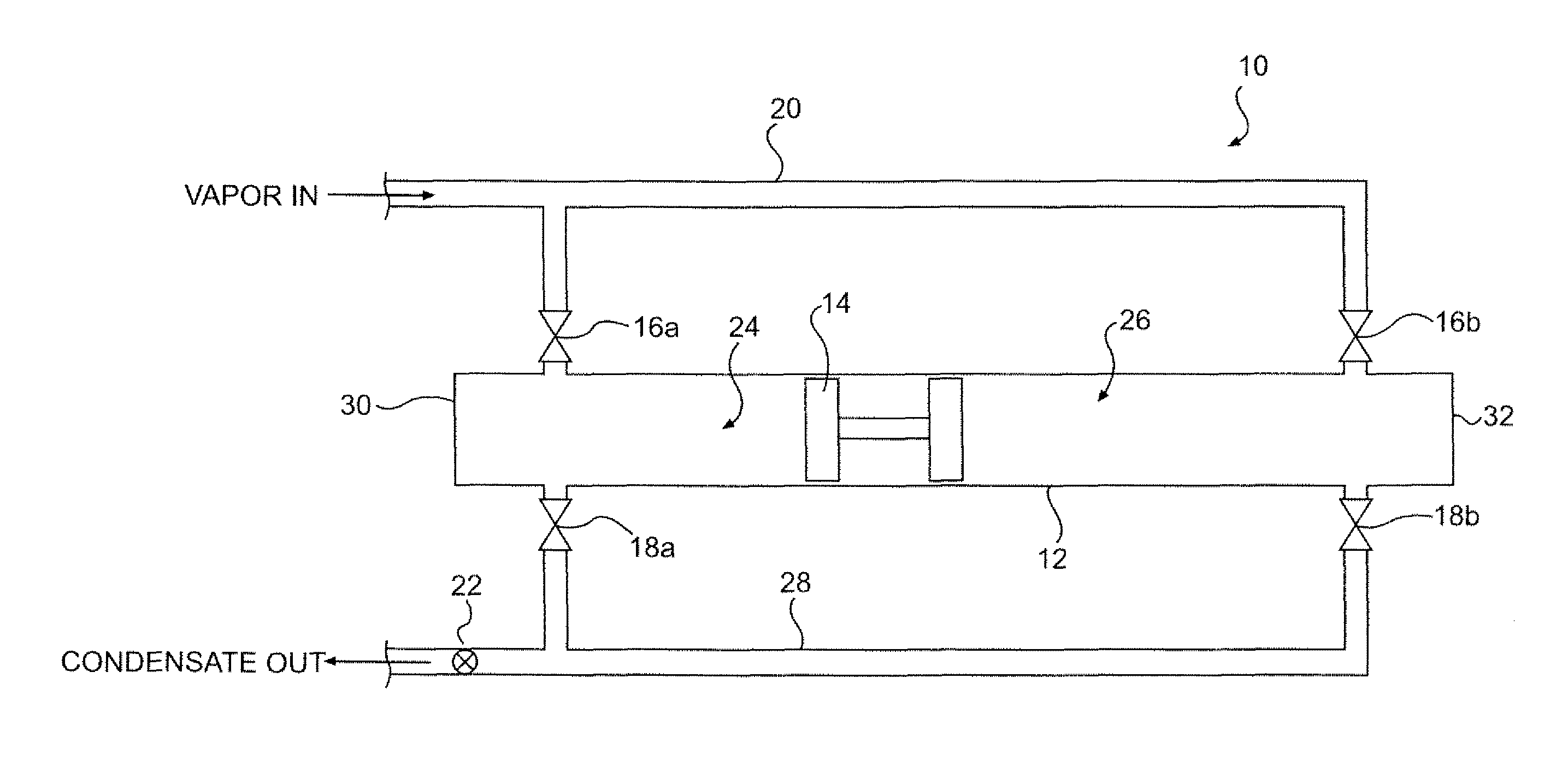
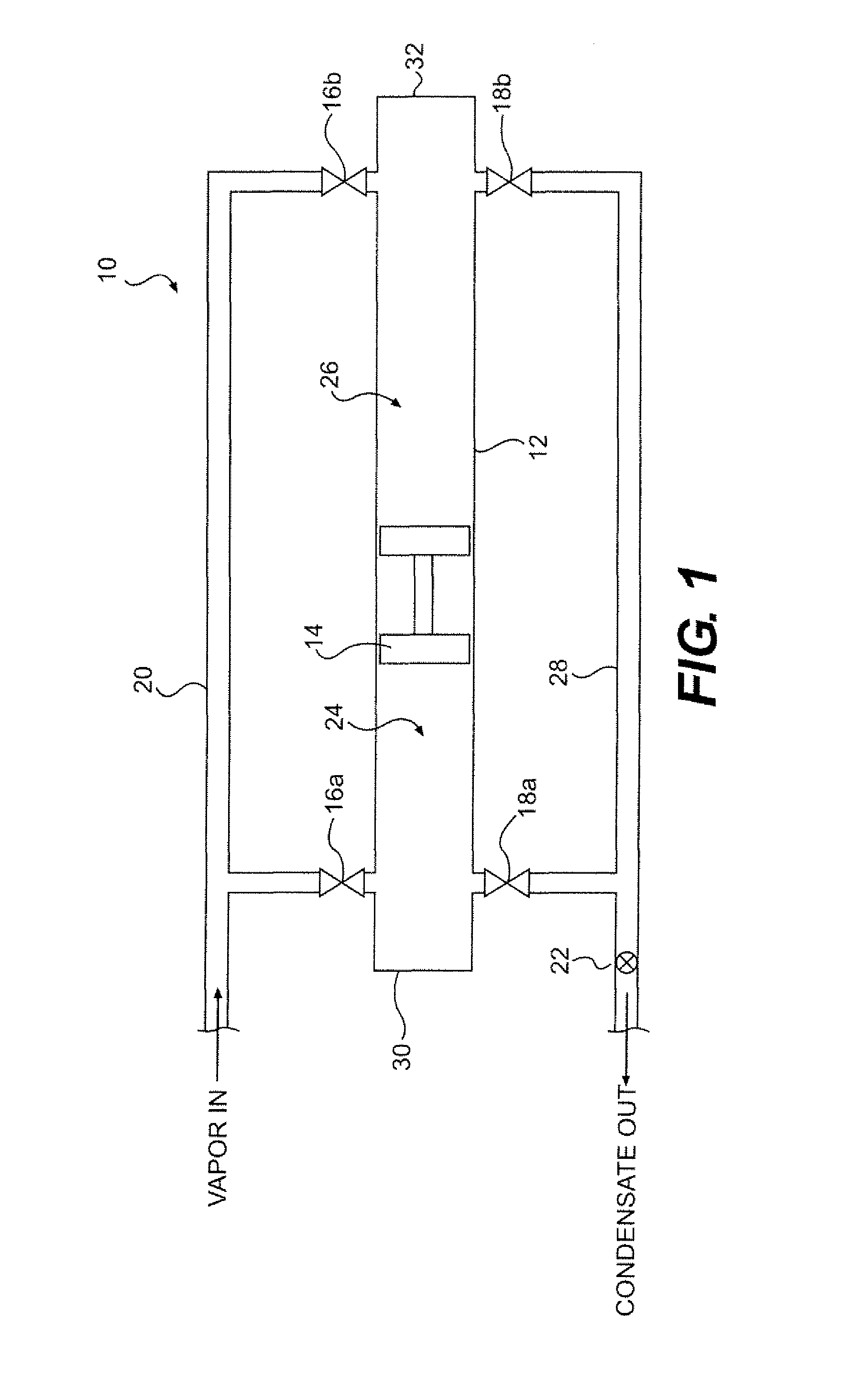
[0020]Referring now to FIG. 1, a schematic block diagram of a heat pipe radiator is illustrated, in accordance with one embodiment of the present invention. The heat pipe radiator 10 comprises a radiator tube 12, a free-piston 14, a first inlet valve 16a, a second inlet valve 16b, a first drain valve 18a, a second drain valve 18b, and a pump 22. The radiator tube 12 typically has a straight cylindrical shape, although other shapes may be possible. The radi...


PUM


Abstract

An open loop heat pipe radiator comprises a radiator tube and a free-piston. The radiator tube has a first end, a second end, and a tube wall, and the tube wall has an inner surface and an outer surface. The free-piston is enclosed within the radiator tube and is capable of movement within the radiator tube between the first and second ends. The free-piston defines a first space between the free-piston, the first end, and the tube wall, and further defines a second space between the free-piston, the second end, and the tube wall. A gaseous-state working fluid, which was evaporated to remove waste heat, alternately enters the first and second spaces, and the free-piston wipes condensed working fluid from the inner surface of the tube wall as the free-piston alternately moves between the first and second ends. The condensed working fluid is then pumped back to the heat source.

Description

FIELD OF THE INVENTION[0001]The present invention generally relates to cooling systems and, more particularly, relates to heat pipe radiators.BACKGROUND OF THE INVENTION[0002]The ability to eliminate waste heat is an important feature of any power generation or power transmitting system, and particularly of space-based power generation or power transmitting systems. Eliminating waste heat is also an important need for human or robotic activity in space. Both nuclear and concentrator types of solar space-based sources of electricity result in the production of several times as much unusable power as is converted to electricity. The only continuous method of eliminating this excess energy in space is by radiation. The high cost of lifting payloads to orbit necessitates thermal management systems with the minimum mass possible.[0003]The rate of radiation heat transfer is proportional to (T4hot−T4cold), where generally Thot>>Tcold. Hence, having the maximum Thot possible for a giv...

Claims


Application Information

Patent Timeline
Patent Type & Authority Patents(United States)
IPC IPC(8): F28D15/02F28D15/06
CPCF28D15/0266F28D15/025F28D15/06
Inventor WEINSTEIN, LEONARD M.
Owner NASA
Why Eureka
Try Eureka