Central receiver solar system comprising a heliostat field

a solar system and central receiver technology, applied in the direction of solar heat collectors for particular environments, solar radiation concentration, moving/orienting solar heat collectors, etc., can solve the problems of less efficient heliostats, power increases at the receiver, and decreases in power per heliostat, so as to achieve greater side length ratio, reduce efficiency, and improve efficiency

Active Publication Date: 2015-08-04
SCHRAMEK PHILIPP DR
View PDF21 Cites 0 Cited by
  • Summary
  • Abstract
  • Description
  • Claims
  • Application Information

AI Technical Summary

Benefits of technology

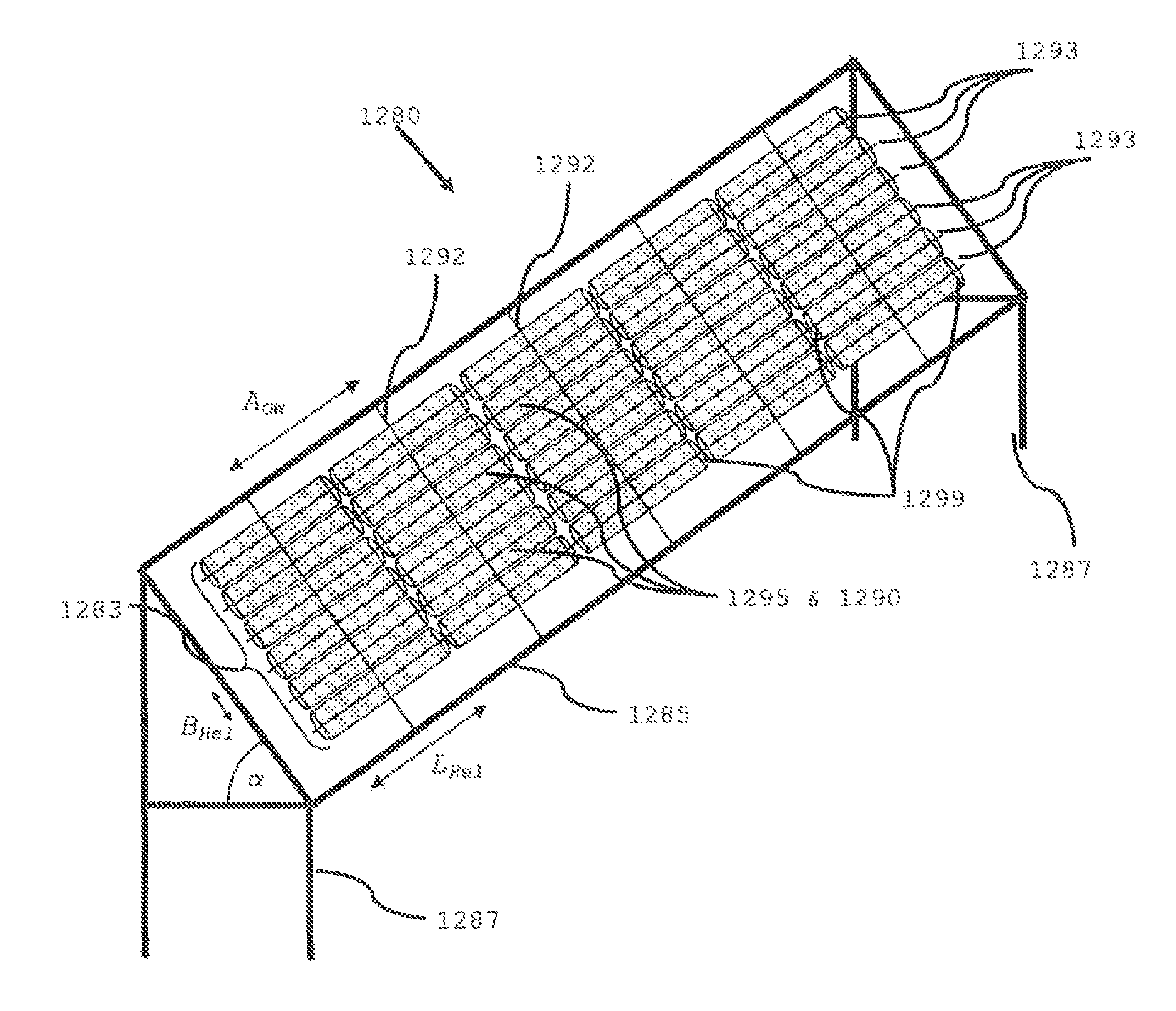
[0046]Accordingly, the one or more receivers can be held above a heliostat field so that heliostats can also be installed directly underneath the receiver. For a downwardly directed receiver, heliostats in the region underneath the receiver have especially large efficiencies. Thanks to the installation of heliostats with rectangular reflectors in which the first rotary axle is parallel to the mounting surface, or heliostats with rigid horizontal axle suspension (FHA), the heliostats with common mounting surface can be installed in rows (preferably in the east-west direction) with very high mounting density.
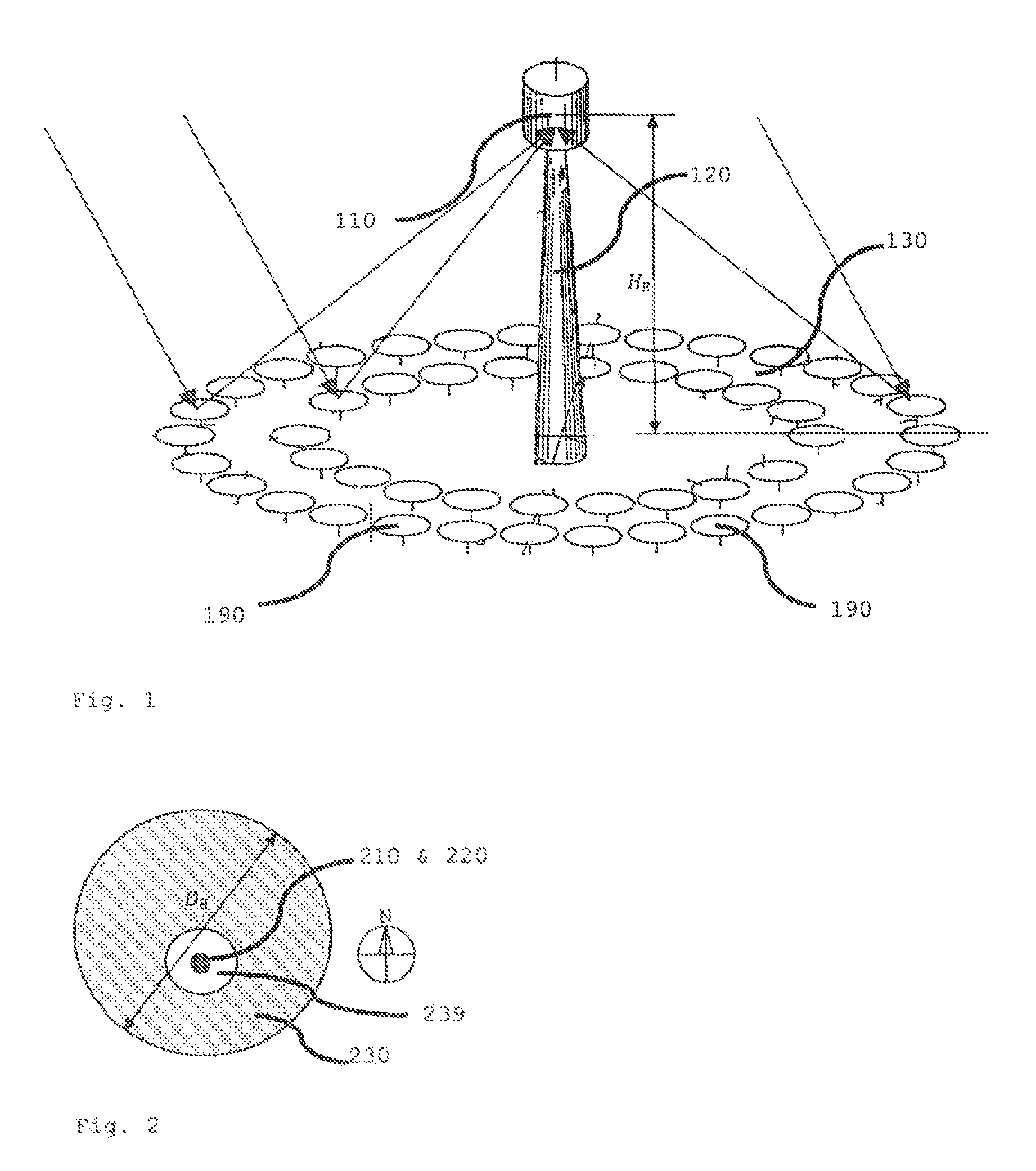
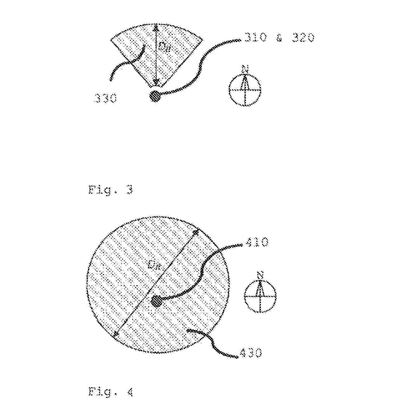
[0055]a. The system according to the invention has a near field that extends beneath the receiver, in which heliostats with the highest efficiency are installed with reflector surface density ρ greater than 60% with heliostats having rectangular reflector surfaces and heliostats having rigid horizontal axle suspension (FHA) or rigid quasipolar axle suspension (FQA).b. The heliostat field is continuous and uninterrupted, like the surrounding heliostat field, which has a recess in the region about the tower where the system according to the invention has heliostats with the highest efficiency.c. The system according to the invention has a receiver with downward directed aperture or absorber surface, which is advantageous not only because heliostats with the highest efficiency can be installed in the near field, but also because the convection and radiation losses are minimized with a receiver directed downward to the heliostat field.d. The receiver is suspended from a support structure, which reaches across the heliostat field, making it possible to point the receiver at a near field beneath the receiver, which results in higher efficiencies of the heliostats in the near field.e. The system according to the invention has substantially smaller heliostat fields in the sense of smaller reflector surface and smaller ground surface for the same radiation power on the target surface of the receiver at the designed time.

Problems solved by technology

With increasing number of heliostats, the radiation power at the receiver increases, but the power increase per heliostat decreases with each additional, less efficient heliostat.

Method used


Image

  • Central receiver solar system comprising a heliostat field
  • Central receiver solar system comprising a heliostat field
  • Central receiver solar system comprising a heliostat field

Examples


embodiment 1

Sample Embodiment 1

[0108]A sample layout of a central receiver solar system based on this patent was designed with the following properties:

[0109]Assumptions for Design of the Central Receiver Solar System

Designed time: 21 June, 12 noon, solar time.

Location: latitude 34° N, north latitude, (e.g., North Africa or Southern California, USA).

Assumption: direct normal radiation (solar radiation power) at the designed time: 1000 W / m2.

Radiation power (thermal power in Megawatt—MWth) on the target surface of the receiver at the design time: 140 MWth.

[0110]Receiver

[0111]The receiver used is a hohlraum receiver, as depicted in FIG. 15, where the absorber 1515 is situated in a cavity 1512. The solar radiation enters through the optical opening, or aperture 1511, into the cavity 1512 and impinges there on the absorber 1515, which changes the solar radiation into heat. The absorber 1515 can also have different shapes and structures. The normal vector nR of the aperture surface points downward. B...

embodiment 2

Sample Embodiment 2

[0146]A further sample design for a central receiver solar system based on this patent was designed with the following properties, making use of the invented type of heliostats with rigid quasipolar axle suspension (FQA):

[0147]Assumptions for Design of the Central Receiver Solar System

[0148]Designed time: 21 June, 12 noon, solar time.

[0149]Location: latitude 34° N, north latitude, (e.g., North Africa or Southern California, USA).

[0150]Assumption: direct normal radiation (solar radiation power) at the designed time: 1000 W / m2.

[0151]Receiver

[0152]The receiver used is a receiver with external absorber, as shown in FIG. 20, there is an absorber 2015 at one side of the receiver. The surface of the absorber 2015 is thus also equal to the optical opening of the receiver, or aperture 2011. In other cases, the absorber 2015 can also have a nonflat surface. The normal vector nR of the absorber surface points downward. BR—NS is the width of the rectangular absorber 2015 in t...

embodiment 3

Sample Embodiment 3

[0193]A further sample design for a small central receiver solar system based on this patent making use of heliostats with rigid horizontal axle suspension in a heliostat field consisting solely of a near field and where the support structure is a revolving tower crane with jib, enabling movement of the receiver in up to three dimensions:

[0194]Assumptions for Design of the Central Receiver Solar System

Designed time: 21 June, 12 noon, solar time.

Location: latitude 34° N, north latitude, (e.g., North Africa or Southern California, USA).

Assumption: direct normal radiation (solar radiation power) at the designed time: 1000 W / m2.

Radiation power (thermal power in Megawatt—MWth) on the target surface of the receiver at the design time: 2 MWth.

[0195]Receiver

[0196]The receiver used is a hohlraum receiver, as depicted in FIG. 15. The normal vector nR of the aperture surface points downward. BR—NS is the width of the rectangular aperture 1511 in the north-south direction and...


PUM


Abstract

The aim of the invention is to build central receiver solar power plants in which the heliostat fields can be used more efficiently. To achieve said aim, a heliostat field consisting of a near field having a uniform reflector surface density ρ of more than 60% is preferably combined with a far field whose reflector surface density ρ decreases as the distance from the receiver increases. The invention also comprises central receiver solar power plants which consist exclusively of a near field having a uniform reflector surface density ρ of more than 60%. The high reflector surface density ρ in the near field and in areas of the far field is achieved by the use of heliostats having rectangular reflectors and a rigid horizontal axle suspension (FHA) or, alternatively, by heliostats having rectangular reflectors and a rigid quasipolar axle suspension (FQA). The heliostat field concentrates the solar radiation on a receiver whose target surface, aperture, thermal absorber or photovoltaic absorber has a normal vector which is directed downward to the heliostat field that extends below the receiver in the directions North, East, South and West. The receiver is mounted in a suspended manner to a support structure that extends over the heliostat field.

Description

FIELD OF THE INVENTION[0001]The invention concerns a method of designing a heliostat field of a central receiver solar system and a central receiver solar system with a heliostat field, consisting of one or more receivers, a plurality of heliostats forming the heliostat field, which are arranged on a preferably level overall ground surface, wherein the heliostat has a reflector which can be positioned about two rotary axles, which reflects the solar radiation onto the target surface of the one or more receivers as the position of the sun changes, while the target surface is the aperture, the thermal absorber or the photovoltaic absorber of the particular receiver, and the heliostat has a first rotary axle and a second rotary axle, perpendicular to the first one, being arranged on a mounting surface, while the first rotary axle is firmly situated with respect to the mounting surface and the second rotary axle is firmly situated with respect to the reflector, and a supporting structur...

Claims


Application Information

Patent Timeline
Patent Type & Authority Patents(United States)
IPC IPC(8): F24J2/10F24J2/38F24J2/07F24J2/16F24J2/54F24J2/02G06F17/50F24S20/20F24S20/30F24S23/00F24S23/70F24S23/77F24S50/20
CPCF24J2/07F24J2/1047F24J2/16F24J2/542F24J2/5424F24J2/02F24J2/38G06F17/50F24J2002/075F24J2002/108Y02E10/41Y02E10/47F24J2200/04F24S2201/00F24S20/20F24S23/80F24S23/77F24S30/452F24S30/455F24S2020/23F24S2023/872F24S50/20G06F30/00Y02E10/40
Inventor SCHRAMEK, PHILIPPMAASS, JOACHIM
Owner SCHRAMEK PHILIPP DR
Why Eureka
Try Eureka