System and method for deploying an endoluminal prosthesis at a surgical site

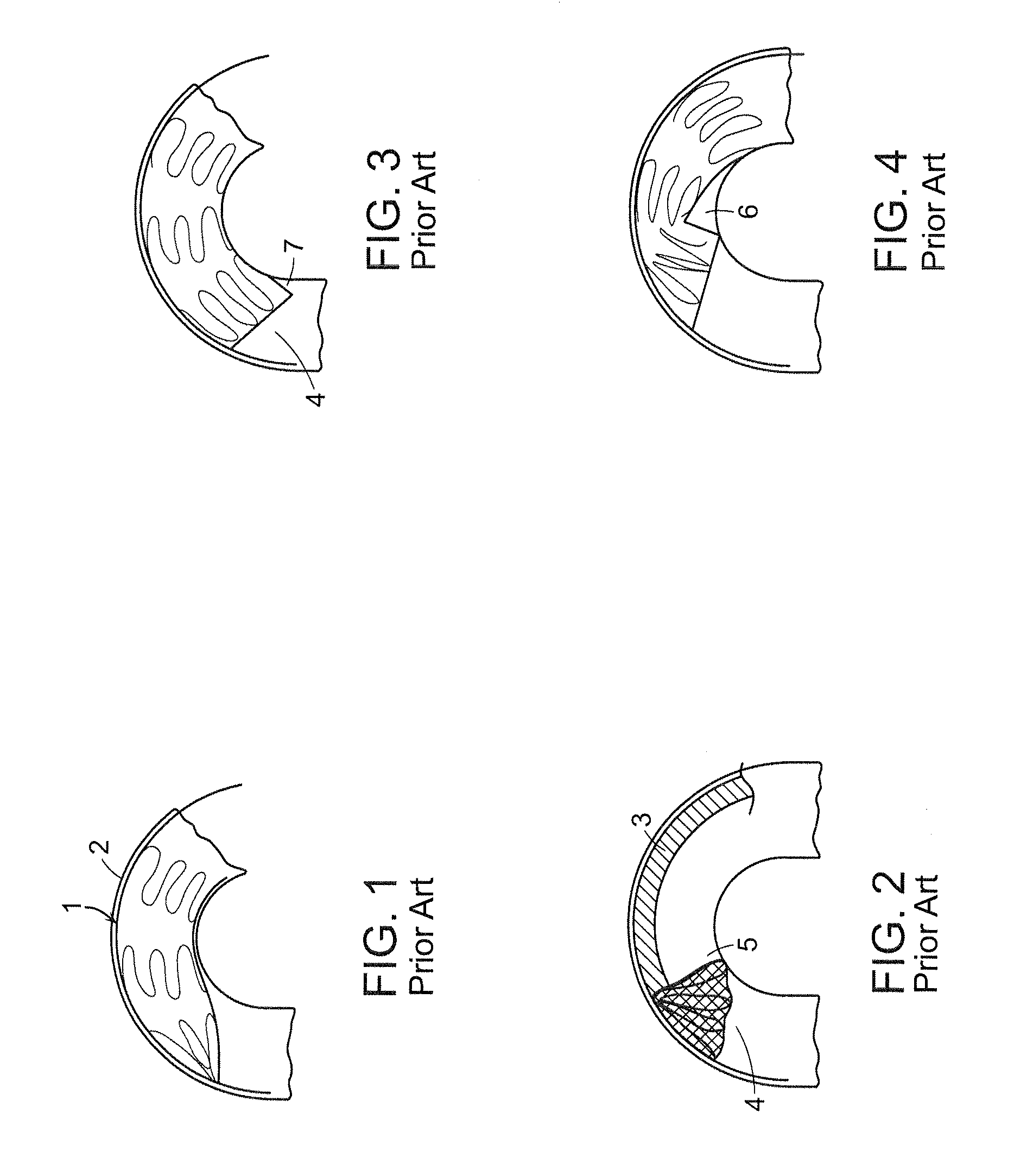
a surgical site and prosthesis technology, applied in the field of system and method for deploying an endoluminal prosthesis at a surgical site, can solve the problems of proximal end (cranially), stent graft not being able to properly align with the arterial wall, and the proximal end of the stent graft not being able to form a seal with the artery

Active Publication Date: 2015-08-11
BOLTON MEDICAL INC
View PDF559 Cites 102 Cited by
  • Summary
  • Abstract
  • Description
  • Claims
  • Application Information

AI Technical Summary

Benefits of technology

[0019]This invention has many advantages. For example, the supporting wire of the system for implanting a prosthesis provides longitudinal support for at least a portion of the proximal end of a stent graft, such as a portion of the proximal end of the stent graft that is located an inferior, or inner, portion of a curve, of the aortic arch. This longitudinal restraint limits rotation of a portion of a proximal end of an endoluminal stent at an inferior portion of the aortic arch lumen, thereby causing the proximal end of the stent graft to be properly seated in a plane that is essentially transverse to a major longitudinal axis extending through the aortic lumen at the proximal end of the stent graft. Proper seating of the proximal end of the stent graft prevents seepage of blood beyond and under the prosthesis, thereby increasing the likelihood of successful implant and prolonging useful life of the prosthetic implant. Further, retraction of a nose cone within the stent graft prior to its deployment enables the prosthesis to be deployed within an ascending aorta of a patient essentially within abutting relation with a valve of the heart, thereby providing greater flexibility to the surgeon when placing the stent graft within a patient. In addition, retraction of the nose cone within the stent graft prior to deployment within an abdominal aorta of a patient permits refinements in the placement of the stent graft relative to the aneurysm site in the abdominal aorta, thereby providing greater flexibility to the surgeon when placing the stent graft within the patient. Another advantage of the invention is an inner sheath defining at least one through-hole that permits perfusion or continued flow of blood during deployment of a stent graft.
is an inner sheath defining at least one through-hole that permits perfusion or continued flow of blood during deployment of a stent graft.

Problems solved by technology

Several problems can occur by remote deployment of endoluminal prosthesis from a constraining sheath.
For example, if the portion of the aorta where the prosthesis is to be deployed has an extreme tortuosity or tight radius of curvature, such as the arch of the aorta, which is arcuate, or because the disease state of the aorta has caused the aorta to have an irregular shape, simple retraction of the sheath, or sheaths, from the prosthesis can cause the proximal end (cranially, with respect to the patient) of the stent graft to fail to properly align with the arterial wall.
For example, a portion of the proximal end of the stent graft can rotate backward, toward the surgeon, adjacent to the curve in the vessel thereby causing a failure of the proximal end of the stent graft to form a seal with the artery.
Another problem includes the formation of a “bird's beak,” also referred to as a “gap,” caused by the stent graft failing to properly conform to an inferior portion curve of the aorta, which most commonly occurs as a result of a deployment sequence that forces the most proximal covered stent of the prosthesis to be deployed last.
Another problem occurs when the stent graft must be deployed close to the junction between the ascending aorta and the aortic valve.
Specifically, the nose cone employed to assist guidance of the endoluminal prosthesis to the surgical site restricts the ability of the surgeon to deploy the prosthesis contained in the sheath as close to the ascending aorta at its point of origin.

Method used


Image

  • System and method for deploying an endoluminal prosthesis at a surgical site
  • System and method for deploying an endoluminal prosthesis at a surgical site
  • System and method for deploying an endoluminal prosthesis at a surgical site

Examples


Embodiment Construction

[0052]The features and other details of the invention, either as steps of the invention or as combinations of parts of the invention, will now be more particularly described and pointed out in the claims. It will be understood that the particular embodiments of the invention are shown by way of illustration and not as limitations of the invention. The principal features of this invention can be employed in various embodiments without departing from the scope of the invention.

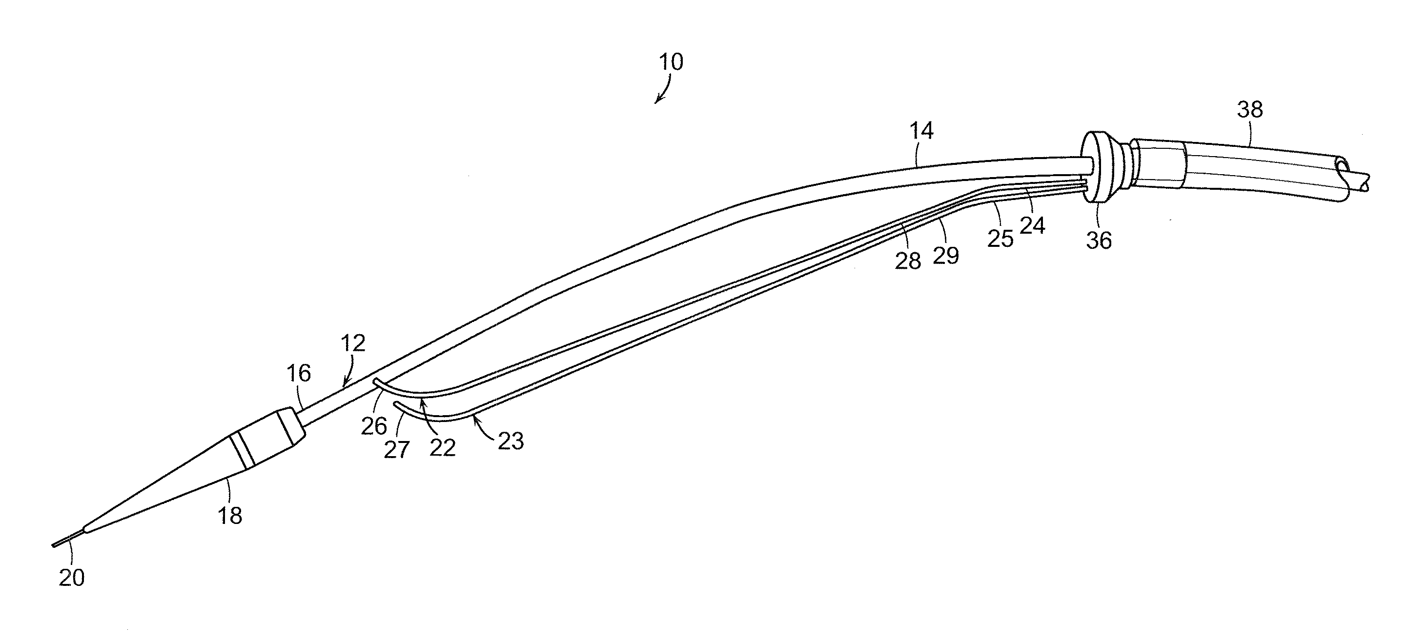
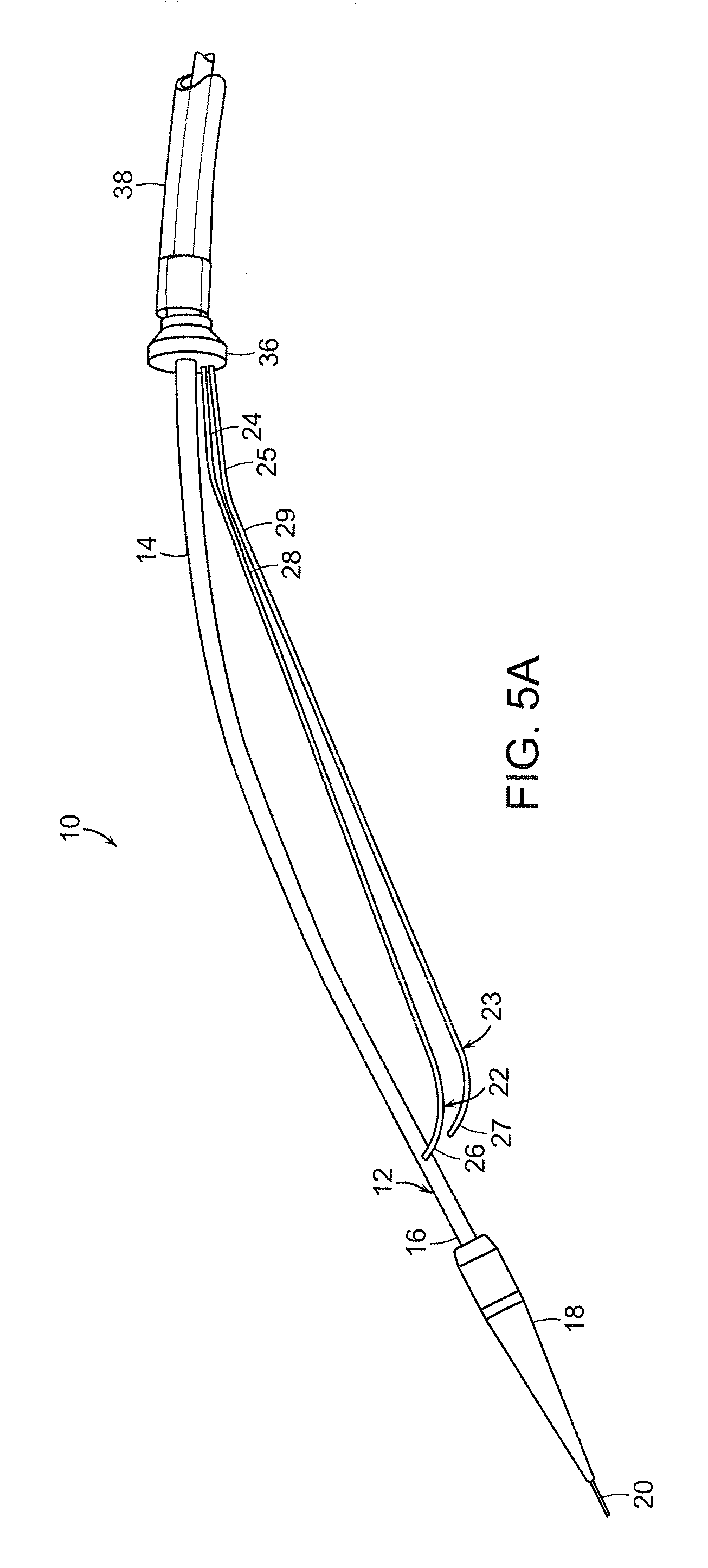
[0053]The present invention generally is directed to a system and method for implanting an endoluminal prosthesis within a vessel (e.g., artery) of a patient. The system and method employ at least one supporting wire to provide longitudinal support to prevent rotation toward the surgeon of a portion of a proximal end of an endoluminal stent graft during deployment of the stent graft. The proximal end of the stent graft is thereby properly seated at the surgical site proximate to an aneurysm or other diseased por...


PUM


Abstract

A system for implanting a prosthesis includes a control lumen and a nose cone affixed at a distal end of the control lumen. At least one supporting wire is affixed at one end, is substantially parallel to a major axis of the control lumen and is free at an opposite end, wherein the free end of at least one of the supporting wires is arcuate. Alternatively, a system for implanting a prosthesis includes at least one suture extending from a nose cone affixed to a distal end of a control lumen. The suture extends from the nose cone to a proximal end to a stent graft extending about the control lumen and from the stent graft to a fixed location on the control lumen. The suture is releasable from the stent graft by remote activation, whereby the suture separates from the nose cone to thereby deploy the stent graft.

Description

RELATED APPLICATIONS[0001]This application claims the benefit of U.S. Provisional Application No. 61 / 160,052, filed on Mar. 13, 2009 and of U.S. Provisional Application No. 61 / 255,339, filed on Oct. 27, 2009. The teachings of these provisional applications are incorporated herein by reference in their entirety.BACKGROUND OF THE INVENTION[0002]Endoluminal prostheses for treatment of arterial disease have come into wide use over the past several years. Typically, such prosthesis include a luminal graft material of woven polyethylene terephthalate (PET) supported by self-expanding stents, which are often formed of a shape memory alloy.[0003]Endoluminal stent grafts, so called because they are deployed within a lumen of a blood vessel, are employed to support diseased arterial tissue, such as arterial tissue that has been weakened to thereby form aneurysms, psuedoaneurysms, dissections, penetrating ulcers, and intramural hematomas. Arteries that are most susceptible to these type of dis...

Claims


Application Information

Patent Timeline
Patent Type & Authority Patents(United States)
IPC IPC(8): A61F2/95A61F2/966A61F2/07
CPCA61F2/95A61F2/07A61F2002/9505A61F2002/9511A61F2002/9665A61F2/966A61F2250/0039A61F2/86A61L27/04
Inventor ARBEFEUILLE, SAMUELCHRISTIAN, FLETCHERMANGUNO, JR., JOSEPH A.CANNING, JOHN C.
Owner BOLTON MEDICAL INC
Why Eureka
Try Eureka