Method and system for binary flow turbine control

a flow turbine and flow control technology, applied in the direction of electric control, ignition automatic control, machines/engines, etc., can solve the problems of limiting the amount of residuals that can be tolerated in the engine, requiring further dilution, and limited residual amount actually delivered to the engine, so as to improve fuel economy, reduce exhaust emissions, and increase engine dilution

Active Publication Date: 2015-08-11
FORD GLOBAL TECH LLC
View PDF18 Cites 14 Cited by
  • Summary
  • Abstract
  • Description
  • Claims
  • Application Information

AI Technical Summary

Benefits of technology

[0003]In an effort to meet stringent federal government emissions standards, engine systems may be configured with exhaust gas recirculation (EGR) systems wherein at least a portion of the exhaust gas is recirculated to the engine intake. The EGR systems may include low-pressure EGR systems that recirculate exhaust gas from downstream of an exhaust turbine to upstream of an exhaust compressor, as well as high-pressure EGR systems that recirculate exhaust gas from upstream of an exhaust turbine to downstream of an exhaust compressor. Such EGR systems enable an increase in engine dilution, decrease in exhaust emissions, and improvements in fuel economy.
[0006]The inventors herein have recognized that engine dilution issues may be overcome in a boosted engine system that uses a binary flow turbine. In one example, managing of residuals may be improved by a method comprising adjusting a scroll valve coupled to an inlet of an outer scroll of a multi-scroll exhaust turbine responsive to engine dilution. By adjusting the scroll valve based on engine dilution, exhaust residuals may be managed even when a combustion stability limit is approached, and / or an opening or closing limit of an EGR valve is approached. For high pressure EGR (HP-EGR) systems, closing the scroll valve can provide higher exhaust manifold pressure so that exhaust manifold pressure is above intake manifold pressure, thereby allowing HP-EGR to flow.
[0007]In one example, in response to an engine dilution request being higher than an engine dilution that can be provided by the EGR system (such as when a high-pressure EGR valve or a low-pressure EGR valve has reached a fully open position), the engine dilution request may be provided by decreasing the opening of the scroll valve. Wastegate adjustments may be coordinated with the scroll valve adjustment to further improve managing of the exhaust residuals. Alternatively, if combustion stability limits are reached, the scroll valve may be moved to a more open position to quickly reduce residuals by lowering internal and / or HP EGR.
[0009]In this way, scroll valve adjustments in a binary flow turbine can be advantageously used to manage engine dilution and residual delivery. By closing the valve when the opening limit of an EGR valve is reached, further engine dilution may be provided. By extending the range of engine operating conditions over which exhaust gas can be recirculated, engine dilution benefits are maximized, improving engine performance and fuel economy.

Problems solved by technology

However the inventors herein have recognized potential issues with such systems.
As one example, there may be limits to the amount of residuals that can be tolerated in the engine due to combustion stability constraints.
For example, due to engine combustion stability limits at the prevalent engine operating conditions, even though further engine dilution is possible (e.g., by further opening an EGR valve), an amount of residuals actually delivered to the engine may be limited (e.g., at high loads) so as to deliver the demanded torque.
Conversely, there may be conditions where further dilution is required but is not deliverable due to a limit of the EGR system.
Likewise, if dilution is required to be reduced when one or more of an EGR valve of the high-pressure EGR system and the low-pressure EGR system is fully closed (that is, at a lower closing limit), a further decrease in dilution may not be provided.
In each case, engine performance is degraded due to a limit (combustion stability limit or valve opening / closing limit) being reached.

Method used


Image

  • Method and system for binary flow turbine control
  • Method and system for binary flow turbine control
  • Method and system for binary flow turbine control

Examples


Embodiment Construction

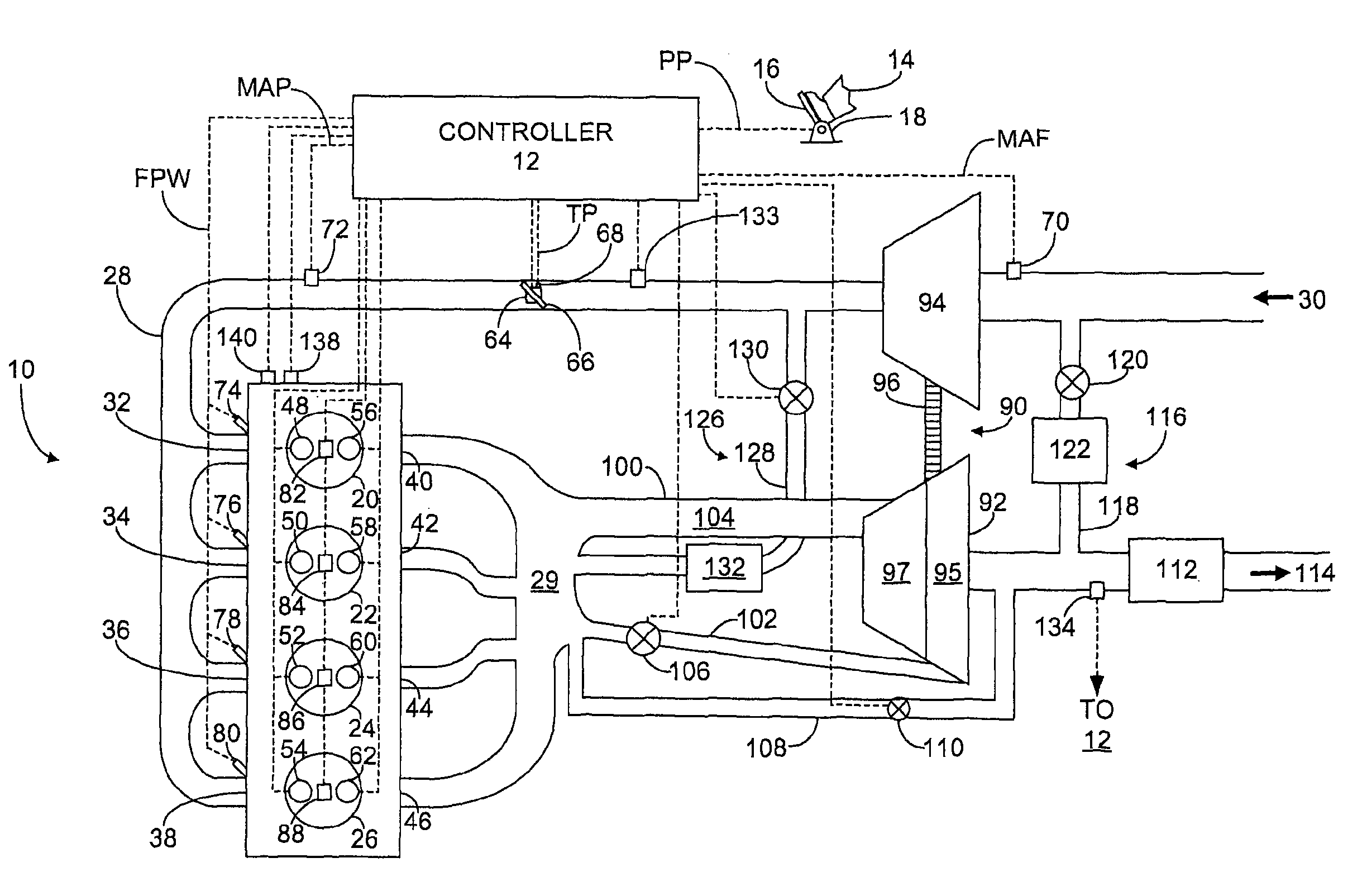
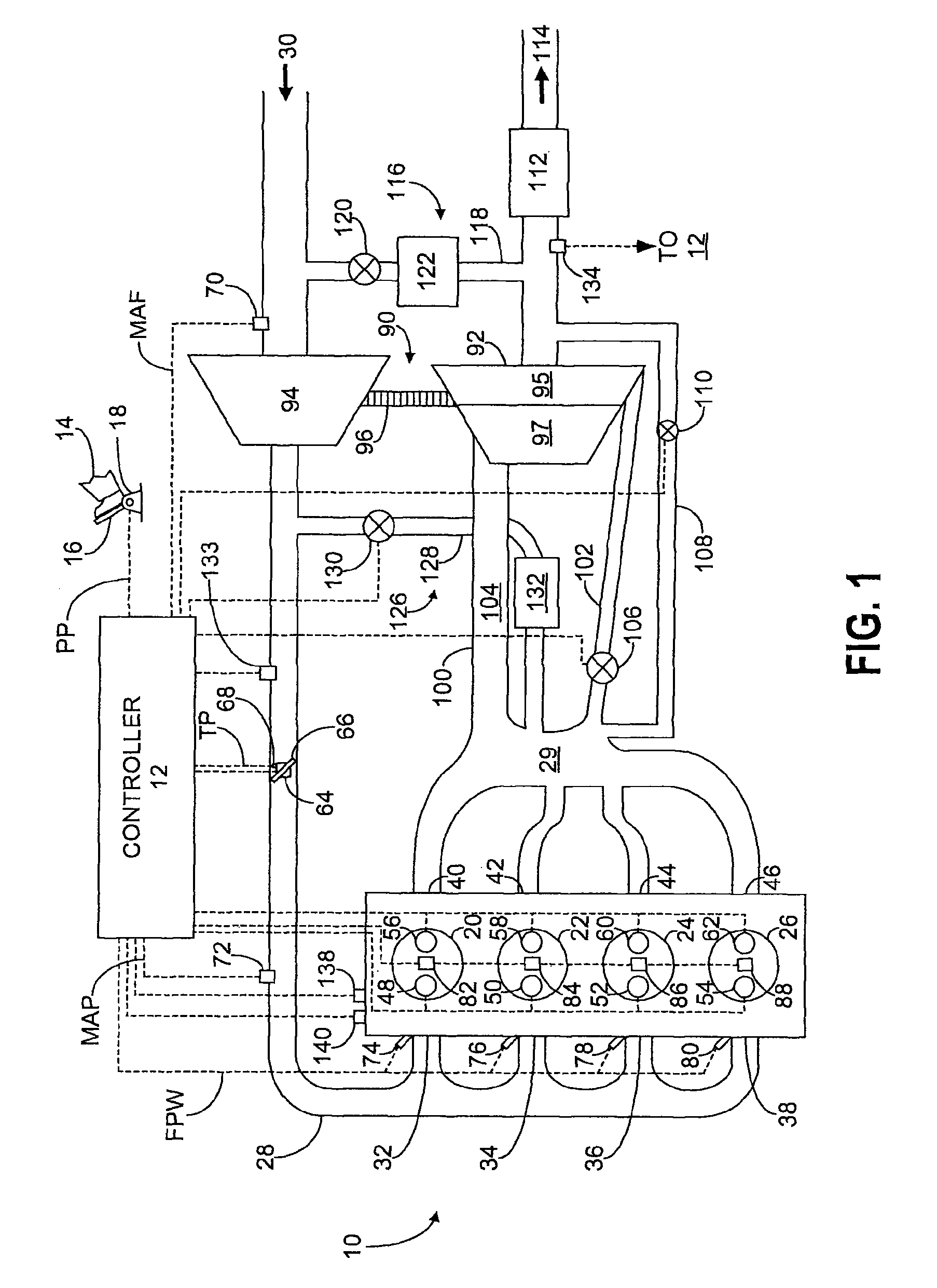
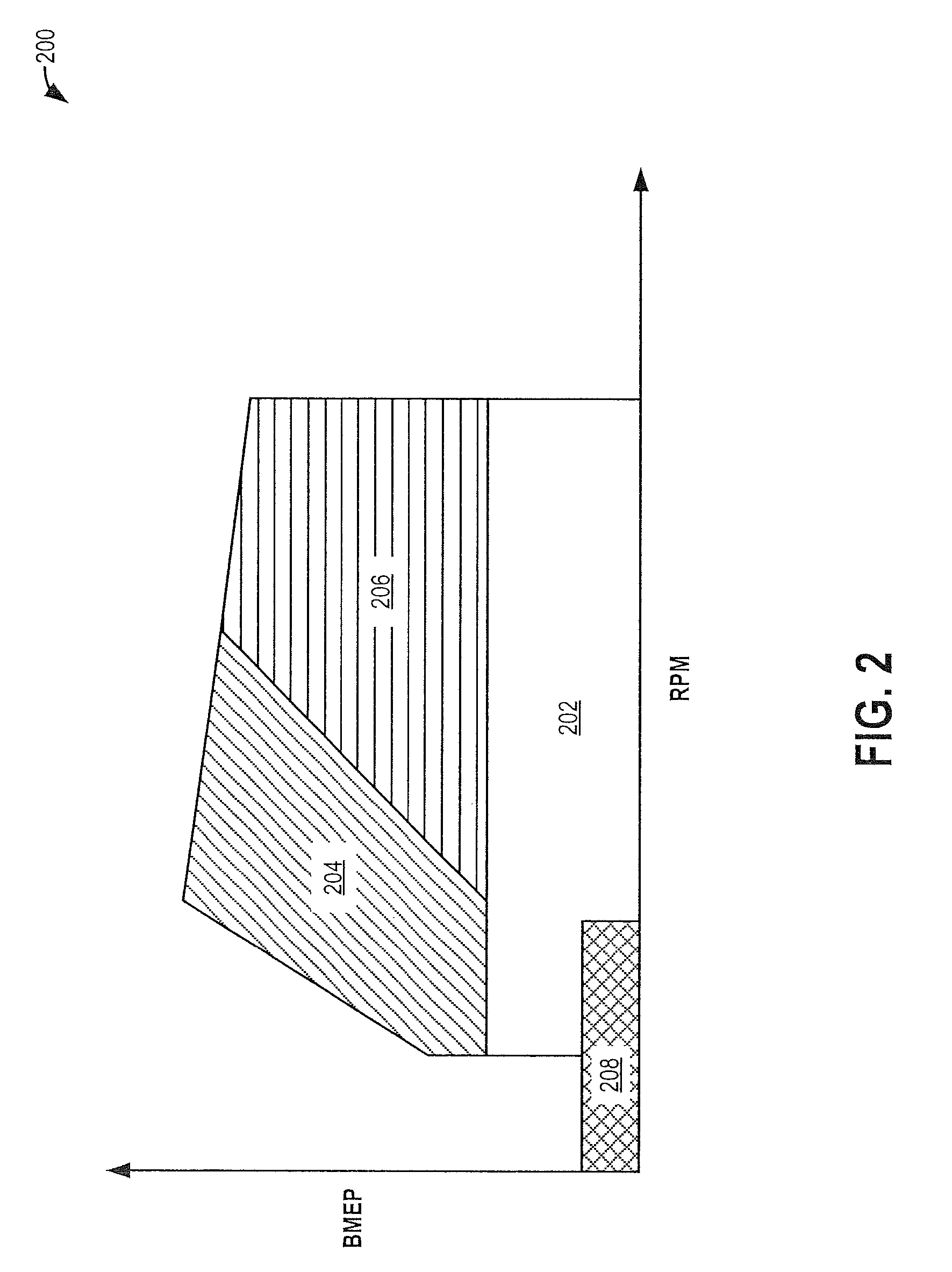
[0016]The following description relates to systems and methods for operating a boosted engine including a binary flow turbine and an exhaust gas recirculation (EGR) system, as shown in FIG. 1. A controller may be configured to perform a routine, such as the routine of FIG. 5, to adjust a position of a scroll valve of the turbine (such as from an initial position) based on various engine operating conditions. Selection of an initial scroll valve schedule may be based on engine speed-load maps such as those shown at FIGS. 2-3. For example, the scroll valve position may be adjusted during engine starts (FIG. 6) to reduce engine start emissions and turbocharger whine. The valve position may be adjusted during torque transients (FIG. 7), such as a tip-in, to reduce turbo lag. The valve position may also be adjusted responsive to combustion stability limits (FIG. 8), abnormal combustion events (FIG. 9), and engine deactivation (FIG. 10). Various engine actuators may be adjusted based on t...


PUM


Abstract

Methods and systems are provided for adjusting the opening of a scroll valve of a binary flow turbine. Scroll valve adjustments are used at different engine operating conditions to improve engine performance and boost response. Scroll valve adjustments are coordinated with wastegate and EGR valve adjustments for improved engine control.

Description

CROSS REFERENCE TO RELATED APPLICATIONS[0001]This application claims priority to U.S. Patent Application No. 61 / 833,377, filed on Jun. 10, 2013, the entire contents of which are hereby incorporated by reference for all purposes.FIELD[0002]The present application relates to controlling a scroll valve coupled to a binary flow turbine in a boosted engine system.BACKGROUND AND SUMMARY[0003]In an effort to meet stringent federal government emissions standards, engine systems may be configured with exhaust gas recirculation (EGR) systems wherein at least a portion of the exhaust gas is recirculated to the engine intake. The EGR systems may include low-pressure EGR systems that recirculate exhaust gas from downstream of an exhaust turbine to upstream of an exhaust compressor, as well as high-pressure EGR systems that recirculate exhaust gas from upstream of an exhaust turbine to downstream of an exhaust compressor. Such EGR systems enable an increase in engine dilution, decrease in exhaust...

Claims


Application Information

Patent Timeline
Patent Type & Authority Patents(United States)
IPC IPC(8): F02D23/00F02B33/44F02B37/18F02M25/07F02B37/12F02B37/02F02D41/00F02M25/06F02D41/02
CPCF02B37/183F02M25/0706F02M25/0713F02B37/18F02M25/0798F02B37/12F02D41/023F02B37/02F02B37/025F02D41/0007F02D2200/0404F02D2200/1002F02D41/005F02D2041/001F02M26/05F02M26/06F02M26/01F02B37/22F02M26/04F02M26/07Y02T10/12Y02T10/40F02D13/02F02D41/062F02P5/045F02D41/022F02P5/04F02D13/0215F02D41/0052F02D41/04
Inventor BUCKLAND, JULIA HELENDOERING, JEFFREY ALLENBOYER, BRAD ALAN
Owner FORD GLOBAL TECH LLC
Why Eureka
Try Eureka