Exhaust gas emission control system for diesel engine
a technology of exhaust gas and control system, which is applied in the direction of electrical control, machines/engines, mechanical equipment, etc., can solve the problems of rapid rise of dpf temperature, excessive increase of dpf temperature by significant increase of soot regeneration amount, so as to reduce the risk of excessive temperature rise, reduce the risk of dpf deterioration, and improve the effect of regeneration efficiency
- Summary
- Abstract
- Description
- Claims
- Application Information
AI Technical Summary
Benefits of technology
Problems solved by technology
Method used
Image
Examples
first embodiment
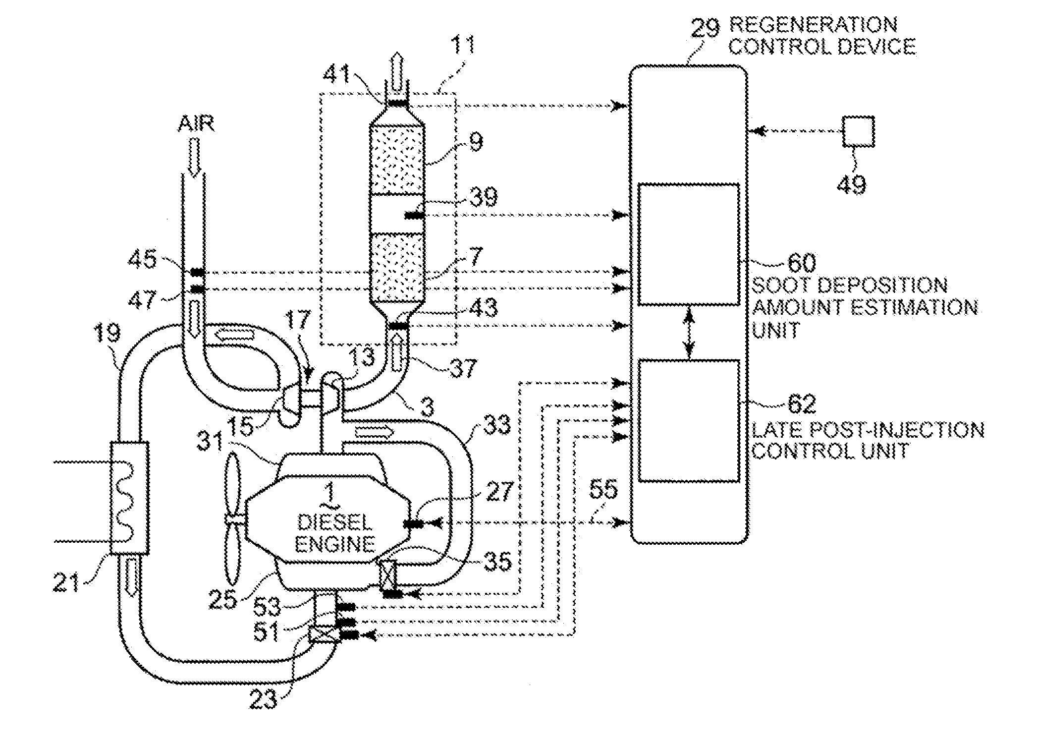
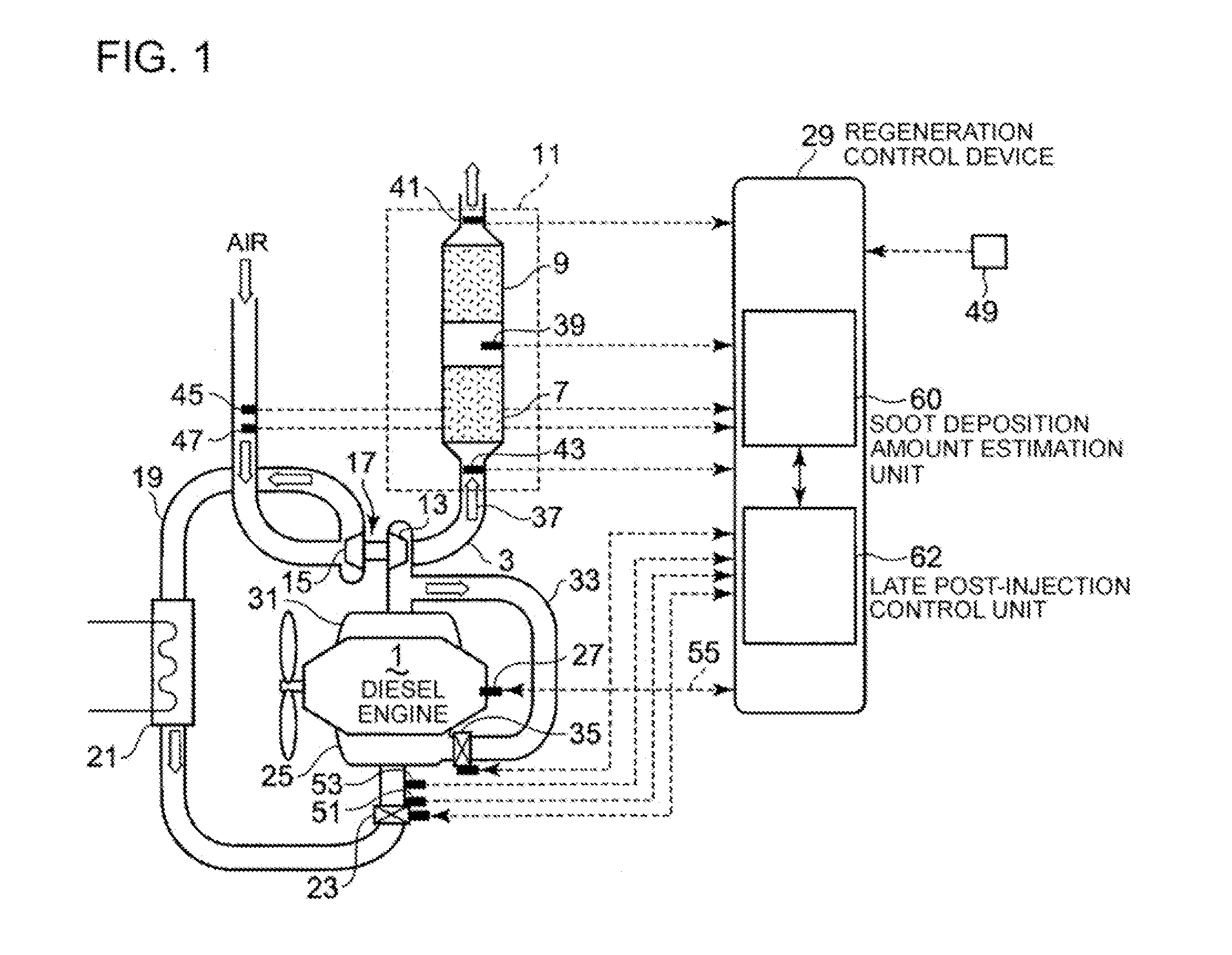
[0083]A first embodiment of the late post-injection control unit 62 provided in the regeneration control device 29 to control the late post-injection amount will be described with reference to FIGS. 5 and 6.
[0084]The late post-injection control unit 62 is characterized feedback controlling the late post-injection amount so that the soot regeneration amount regenerated by the PPF 9 becomes a target soot regeneration amount.
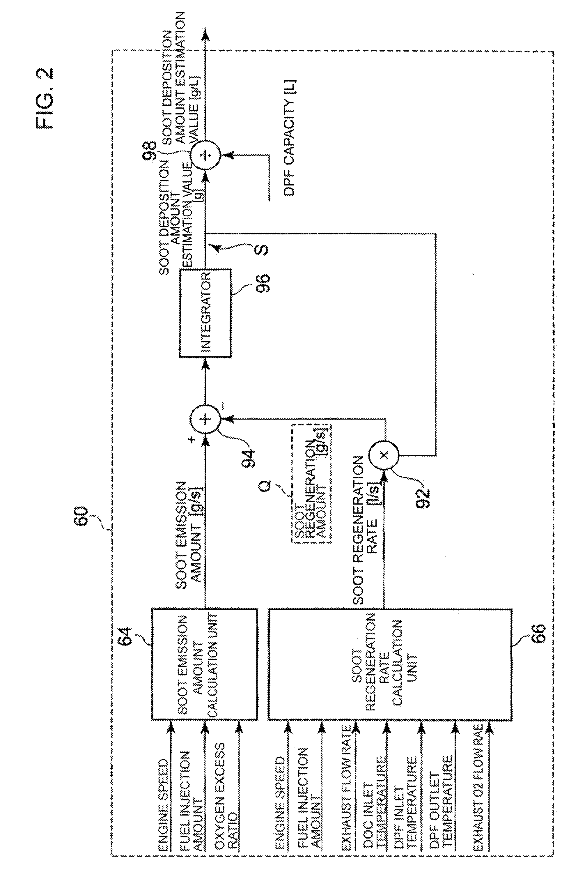
[0085]As shown in FIG. 5, the target soot regeneration amount is set to a constant, whereas the soot regeneration amount is calculated based on an actual engine operating state, and these regeneration amounts are input to an adder 100 which calculates a difference between them. The difference is subjected to feedback PID arithmetic processing by a PID controller 102, and the result is output with its upper limit restricted by a late post-injection amount limiter 104.
[0086]When the soot deposition amount is too small, the soot regeneration amount will be small and t...
second embodiment
[0092]A second embodiment of the late post-injection control unit 62 will be described with reference to FIGS. 7 to 9.
[0093]The second embodiment is different from the first embodiment only in the setting of the target soot regeneration amount, while the other features are the same as those of the first embodiment. Accordingly, like components are assigned with like reference numerals or symbols and description thereof will be omitted.
[0094]As shown in FIG. 7, the target soot regeneration amount is changed according to regeneration time elapsed after the start of late post-injection. The target soot regeneration amount is changed such that it is set to a small value in a stage M1 directly after the start of regeneration, whereas it is set to a greater value than the one in the stage M1 in an intermediate stage M2 where the regeneration has progressed. In a final stage M1, the target soot regeneration amount is again set to a smaller value than the one in the stage M2.
[0095]Since the...
third embodiment
[0107]A third embodiment of the late post-injection control unit 62 will be described with reference to FIGS. 10 to 12.
[0108]The third embodiment is characterized by a rate limiter 110 that is provided to ensure gradual change toward the target soot regeneration amount directly after the start of late post-injection.
[0109]The other configuration features are the some as those of the first embodiment. Therefore, like components are assigned with like reference numerals or symbols and description thereof will be omitted.
[0110]As shown in FIG. 10, a rate limiter 110 is provided in a circuit in which a signal indicating a target soot regeneration amount is input to the adder 100. This improves the overshoot of soot regeneration amount, and prevents the excessive rise of temperature. In FIG. 11, the hold and thin two-dot chain lines represent cases in which the rate limiter is not applied, while the bold and thin solid lines represent cases in which the rate limiter is applied. As seen t...
PUM
 Abstract
Description
Claims
Application Information
 - R&D
- Intellectual Property
- Life Sciences
- Materials
- Tech Scout
- Unparalleled Data Quality
- Higher Quality Content
- 60% Fewer Hallucinations
Browse by: Latest US Patents, China's latest patents, Technical Efficacy Thesaurus, Application Domain, Technology Topic, Popular Technical Reports.
© 2025 PatSnap. All rights reserved.Legal|Privacy policy|Modern Slavery Act Transparency Statement|Sitemap|About US| Contact US: help@patsnap.com


