Carbon fiber composite discharge electrode

a discharge electrode and carbon fiber technology, applied in electrostatic separation, solid separation, chemical apparatus and processes, etc., can solve the problems of not conducting electricity, requiring strong support structures, and expensive and heavy electrodes, and achieves low cost, high strength, and reduced weight of electrodes.

Active Publication Date: 2015-08-25
OHIO UNIV
View PDF24 Cites 14 Cited by
  • Summary
  • Abstract
  • Description
  • Claims
  • Application Information

AI Technical Summary

Benefits of technology

[0010]The invention is a new design of charging electrodes using carbon fibers, nanofibers and nanotubes to generate the corona discharge. A goal of the technology is to produce low cost electrodes that are corrosion resistant. The invention includes carbon fiber electrodes, both with and without a polymer matrix to form a composite Composites are much lighter than metals—so the weight of the electrodes is also reduced. Composites have high strength and can be used to fabricate electrodes of high durability and long operating life.
[0011]The technology has strong potential applications in the pollution control from boiler exhausts, ESPs (specially wet ESPs) and air-purifiers. Composite materials are becoming increasingly popular among various manufacturing processes that use electrodes. ESPs are widely used to remove particulate matter from the stacks of coal-fired power plants. The technology could help provide cost savings due to high strength and corrosion-resistant properties of the electrodes.
[0012]The invention has several advantages over other commercially available charging electrodes, including improvement in the charging characteristics of the electrode; lower cost of the electrodes due to use of inexpensive, lighter materials and simpler design; lower cost of overall equipment as the cost of any supporting structure is eliminated or reduced. Furthermore, variation in the composition and physical configuration of the electrodes is feasible depending on the requirements and conditions of their operation, and collection efficiency is improved due to improvement in the airflow pattern. Corrosion resistance is enhanced in environments that would adversely affect metallic electrodes.

Problems solved by technology

The sharp spikes of the charging electrodes are also typically made of an expensive alloy (e.g., HASTELLOY brand alloy) to avoid or mitigate corrosion in the harsh environments in which such electrodes are used.
The entire discharge electrode, including the rod, is commonly made of the alloy, causing the electrodes to be expensive and heavy, thereby requiring strong support structures.
Polymers are inexpensive, light and corrosion-resistant, but they do not conduct electricity, and they have poor tensile / flexural strength.

Method used


Image

  • Carbon fiber composite discharge electrode
  • Carbon fiber composite discharge electrode
  • Carbon fiber composite discharge electrode

Examples


Embodiment Construction

[0037]U.S. Provisional Application No. 61 / 224,121 filed Jul. 9, 2009 is incorporated in this application by reference.

[0038]The invention is directed to discharge electrodes made of a combination of one or more of the following components: electrically non-conductive fibers and conductive, non-metallic fibers such as carbon fibers, carbon nanofibers and polymer. Carbon fibers and / or carbon nanofibers (CNFs) are common components in all the electrodes contemplated.

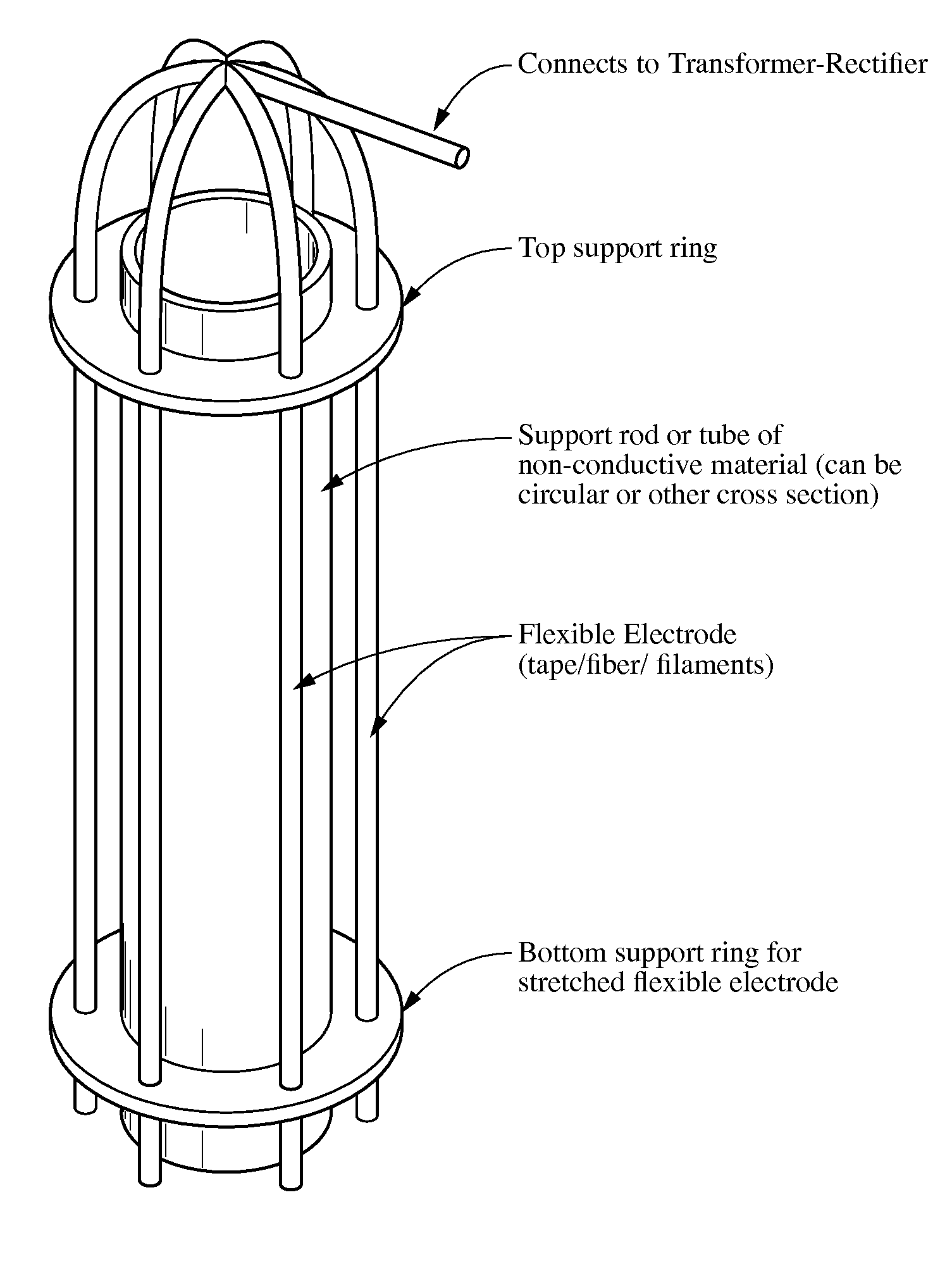
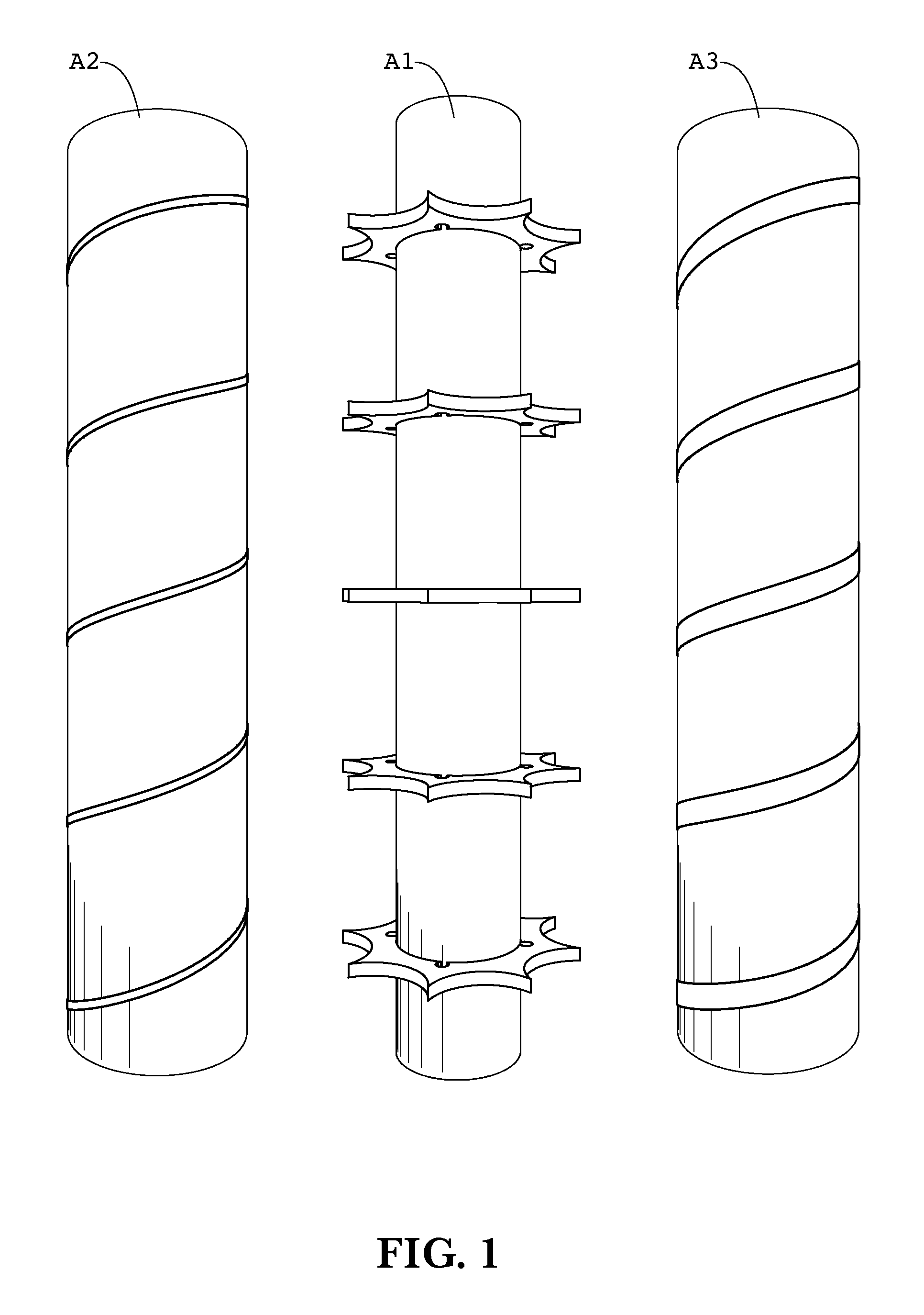
[0039]The fiber and / or composite electrodes can be supported by a support rod, such as by wrapping the conductive filaments around or along the rod, or the fibers can be wound around two substantially parallel, spaced support rods that apply tension to the filaments. In the latter case, the conducting filaments are wound around both supports, producing an array of filaments extending between the rods. In a preferred embodiment, the span extends across a path through which gases flow. In some cases in which nanofibers are in...


PUM

PropertyMeasurementUnit
diameteraaaaaaaaaa
diameteraaaaaaaaaa
lengthsaaaaaaaaaa

Abstract

A discharge electrode using carbon fibers, nanofibers and / or nanotubes to generate the corona discharge. The invention contemplates carbon fiber electrodes with or without a polymer matrix to form a composite, and a supporting configuration in which the fibers are wrapped helically around a supporting rod that extends along the length of the electrode. Another supporting configuration includes the fibers stretched across the gas flow path. Yet another supporting configuration includes mounting the fibers along the length of the support rod substantially parallel to the rod.

Description

CROSS-REFERENCES TO RELATED APPLICATIONS[0001]This application is a submission to enter the national stage under 35 U.S.C. 371 for international application number PCT / US2010 / 41352 having an international filing date of Jul. 8, 2010, for which priority was based upon U.S. Provisional Patent Application No. 61 / 224,121 having a filing date of Jul. 9, 2009.STATEMENT REGARDING FEDERALLY-SPONSORED RESEARCH AND DEVELOPMENT[0002](Not Applicable)REFERENCE TO AN APPENDIX[0003](Not Applicable)BACKGROUND OF THE INVENTION[0004]Charging electrodes are critical components used in electrostatic precipitators (ESPs), which are devices used to collect particles from gas streams, such as the streams from electric power plants burning coal. Examples of such devices are shown in U.S. Pat. No. 6,231,643 to Pasic, et al., and United States Patent Application Publication No. US2008 / 0190296 published Aug. 14, 2008, both of which are incorporated herein by reference.[0005]The most basic ESP contains a row o...

Claims


Application Information

Patent Timeline
Patent Type & Authority Patents(United States)
IPC IPC(8): B03C3/41B03C3/60
CPCB03C3/41B03C3/60B03C2201/04B03C2201/10B03C3/64
Inventor ALAM, M. KHAIRUL
Owner OHIO UNIV
Why Eureka
Try Eureka