Gas bubble generation for coalescing

a technology of gas bubbles and coalescing, which is applied in the directions of transportation and packaging, separation processes, evaporation, etc., can solve the problems of moving into the media bed and clogging the media bed, and achieve the effect of minimizing the clogging of the media bed

Inactive Publication Date: 2015-08-25
SPINTEK FILTRATION
View PDF7 Cites 6 Cited by
  • Summary
  • Abstract
  • Description
  • Claims
  • Application Information

AI Technical Summary

Benefits of technology

[0004]A system and method are provided for minimizing the clogging of the media bed in an ore coalescing chamber. A bubble generator apparatus is provided for the generation of air bubbles for the separation of unwanted undissolved particles or bits, from wanted dissolved bits in the liquid stream, which produces a high proportion of bubbles in the predetermined size range. An initial conduit receives a fluid stream under pressure that contains the wanted and unwanted bits. The bubble generator apparatus includes a source of pressured air that forces air through a diffuser that has tiny holes, to generate bubbles to flow with the liquid stream in the initial conduit and through a mixer. The combination emanating from the mixer passes through a pressure dropping device that reduces the pressure of the combination before its entrance into a separation chamber. In the separation chamber, large bubbles having diameters greater than 100 μm float to the top and are removed, and small bubbles having diameters less than 60 μm flow into a coalescing media bed and tend to clog it. Bubbles in the predetermined size range having diameters from 60 μm to 100 μm cling to unwanted particles and keep them floating in the separation chamber until they are removed from the chamber. The bubbles of the predetermined size range do not cling to dissolved wanted bits, which pass through the coalescing media bed with minimal clogging of the media.
[0005]The system maintains a high proportion of bubbles of a diameter on the order of magnitude of 80 μm, and preferably of a size range in the separation chamber which is usually 60 μm to 100 μm, by providing sensors and valves and by providing a controller that varies operating parameters of the system based on the sensor outputs. A diffuser valve controls the flow rate and pressure of air that is introduced into the liquid stream to create bubbles in the predetermined size range. A pressure dropping valve controls the amount of pressure drop in the liquid-air bubble stream before it enters the separation chamber. If too many large bubbles are present in the separation chamber, the controller operates the pressure dropping valve to increase the pressure of the mixture entering the separation chamber. If too many small bubbles are generated, then the controller operates the pressure dropping valve to decrease the pressure of the mixture entering the separation chamber.

Problems solved by technology

If the bubbles are too small, they rapidly move into the media bed and tend to clog the media bed.
An important problem in the separation of organic particles from wanted bits is the control of bubble size, so as to maintain a large proportion of bubbles in the predetermined size range that effectively remove organic undissolved particles from a separation chamber.

Method used


Image

  • Gas bubble generation for coalescing
  • Gas bubble generation for coalescing

Examples


Embodiment Construction

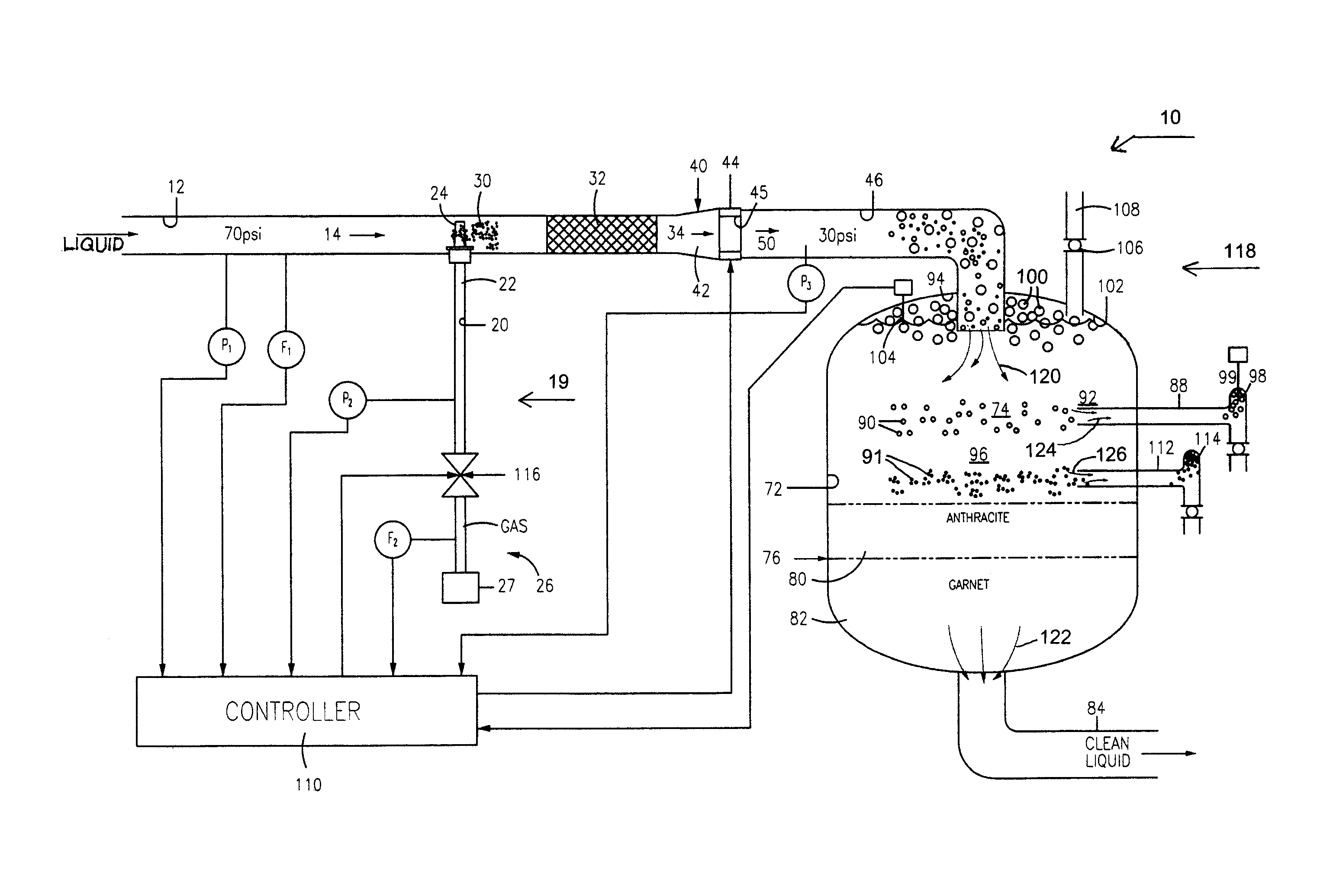
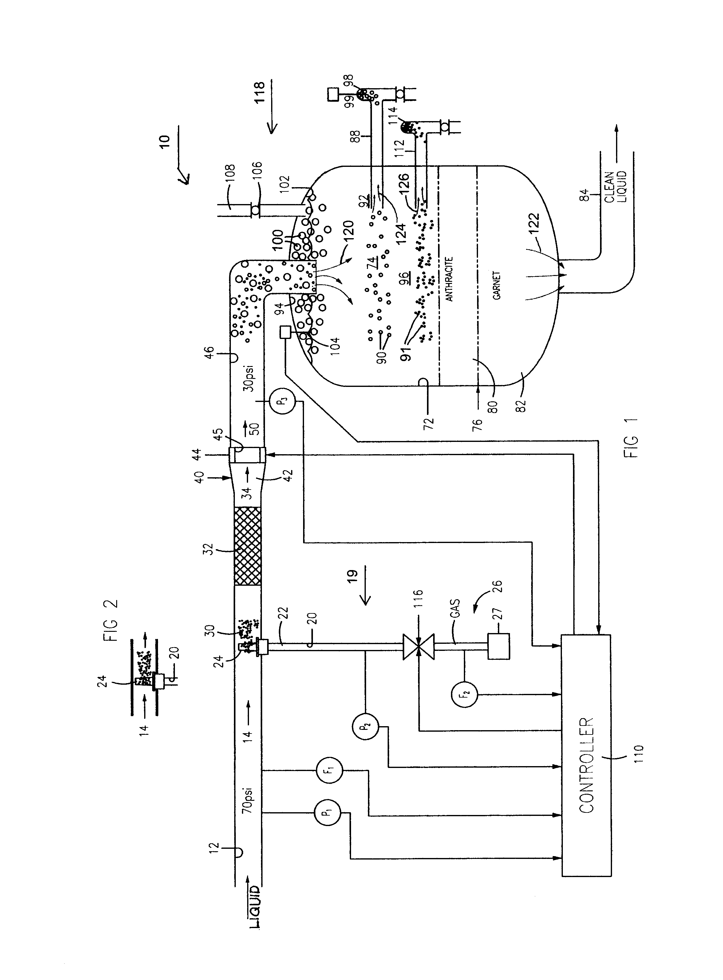
[0009]FIG. 1 illustrates a coalescing system 10 that includes an initial conduit 12 that carries a fluid stream that includes a primarily liquid stream 14 under a pressure P1 such as 70 psi (30 psi to 140 psi) and a flow velocity F1 such as 15 feet per second (7 to 30 fps). In one example, the fluid stream includes dissolved bits of copper and nickel that lie in an acid-water solution such as sulfuric acid and water, along with undissolved particles of hydrocarbons.

[0010]A bubble generator apparatus 19 injects bubbles into the liquid stream. The bubbler generator apparatus includes a diffuser conduit 20 that carries gas 22 under a pressure P2 such as 5 psi (preferably 2 to 10 psi) above the pressure at P1 in the liquid stream 14 and at a gas flow velocity F2 such as 15 feet per second (7 to 30 fps) from a source 26 of pressured air to a diffuser 24 in the liquid stream 14. The initial pressure of the liquid stream in initial conduit 12 is at least 70 psi and the pressured air or oth...


PUM

PropertyMeasurementUnit
diametersaaaaaaaaaa
sizeaaaaaaaaaa
diametersaaaaaaaaaa

Abstract

A system is provided for introducing gas bubbles (usually air bubbles) into a liquid stream to coalesce material such as unwanted bits, or particles, of hydrocarbons that lie in the liquid stream along with wanted dissolved bits of metal, for removal of the hydrocarbons. The system is constructed to produce a large number of bubbles of an optimum range such as 60 to 100 μm which best coalesce the hydrocarbons. A controller receives the outputs of sensors such as pressure and flow rate sensors (P, F) and uses them to make changes in other parameters such as the pressure of air introduced into the liquid stream and the pressure in a third conduit of the liquid-bubble stream.

Description

CROSS-REFERENCE[0001]Applicant claims priority from U.S. Provisional Patent Application Ser. No. 61 / 335,963 filed Jan. 14, 2010.BACKGROUND OF THE INVENTION[0002]Many processes such as the mining of copper and nickel ore, produce molecule-size bits that are wanted such as dissolved bits of copper or nickel, and also produce undissolved bits or particles of material such as liquid hydrocarbons. Liquid organics (compounds such as hydrocarbons that contain carbon) can be removed from a stream by introducing gas bubbles, which are usually air bubbles, into the liquid stream. In a separation chamber, gas bubbles in a predetermined size range, such as 60 μm to 100 μm (2.4 to 4 thousandths inch) cling to the unwanted organic undissolved particles and allow them to be separated from wanted dissolved bits. The bubbles keep the organic particles that flow into a separation chamber, from flowing into a media bed from which almost all remaining contaminants including organic particles, are remov...

Claims


Application Information

Patent Timeline
Patent Type & Authority Patents(United States)
IPC IPC(8): B01D1/00B03D1/24B03D1/14B03B5/60B03D1/00C02F1/24B01F3/04B01F5/04B01F5/06B01F15/00B03D1/02B03D1/04
CPCC02F1/24B01F3/04503B01F5/0451B01F5/0465B01F5/0653B01F5/0657B01F15/00136B01F15/00162B01F15/00357B03D1/028B03D1/04B03D1/1475B03D1/247B01F2215/0431B01F2215/0468B03D1/245C02F2209/005C02F2209/38B01F23/2323B01F25/313311B01F25/3131B01F25/4341B01F25/4336B01F35/2111B01F35/2113B01F35/2213
Inventor GILMOUR, JASONGREENE, WILLIAM A.
Owner SPINTEK FILTRATION
Why Eureka
Try Eureka