Motor control system that detects voltage saturation

a technology of voltage saturation and motor control, applied in the direction of electric generator control, dynamo-electric converter control, dynamo-electric gear control, etc., can solve the problems of motor becoming inability to operate as commanded, motor may be unable to achieve the effect of maintaining machining accuracy

Active Publication Date: 2015-08-25
FANUC LTD
View PDF13 Cites 1 Cited by
  • Summary
  • Abstract
  • Description
  • Claims
  • Application Information

AI Technical Summary

Benefits of technology

[0008]According to an embodiment of the present invention, the host control apparatus is notified of the occurrence of voltage saturation, in response to which the feed speed can be reduced in order to avoid voltage saturation, thus making it possible to maintain the machining accuracy.

Problems solved by technology

In a system such as a machine tool that is driven using a synchronous motor, if the commanded acceleration is large, the maximum torque of the synchronous motor may be exceeded and the motor may become unable to be operated as commanded.
Similarly, depending on the inductance of the synchronous motor, if the commanded jerk is large, the commanded voltage of the synchronous motor may exceed the maximum voltage of a current amplifier and the motor may become unable to be operated as commanded.
However, while patent document 1 describes that the current command value is reduced in the case of voltage saturation, reducing the current command value results in an inability to produce torque as commanded by a torque command.
As a result, the tool cannot be moved to the commanded position at the commanded speed in order to generate the commanded shape; in particular, when generating the contour shape of a workpiece by controlling a plurality of axes, there arises the problem that the accuracy of the shape degrades.

Method used


Image

  • Motor control system that detects voltage saturation
  • Motor control system that detects voltage saturation
  • Motor control system that detects voltage saturation

Examples


embodiment 1

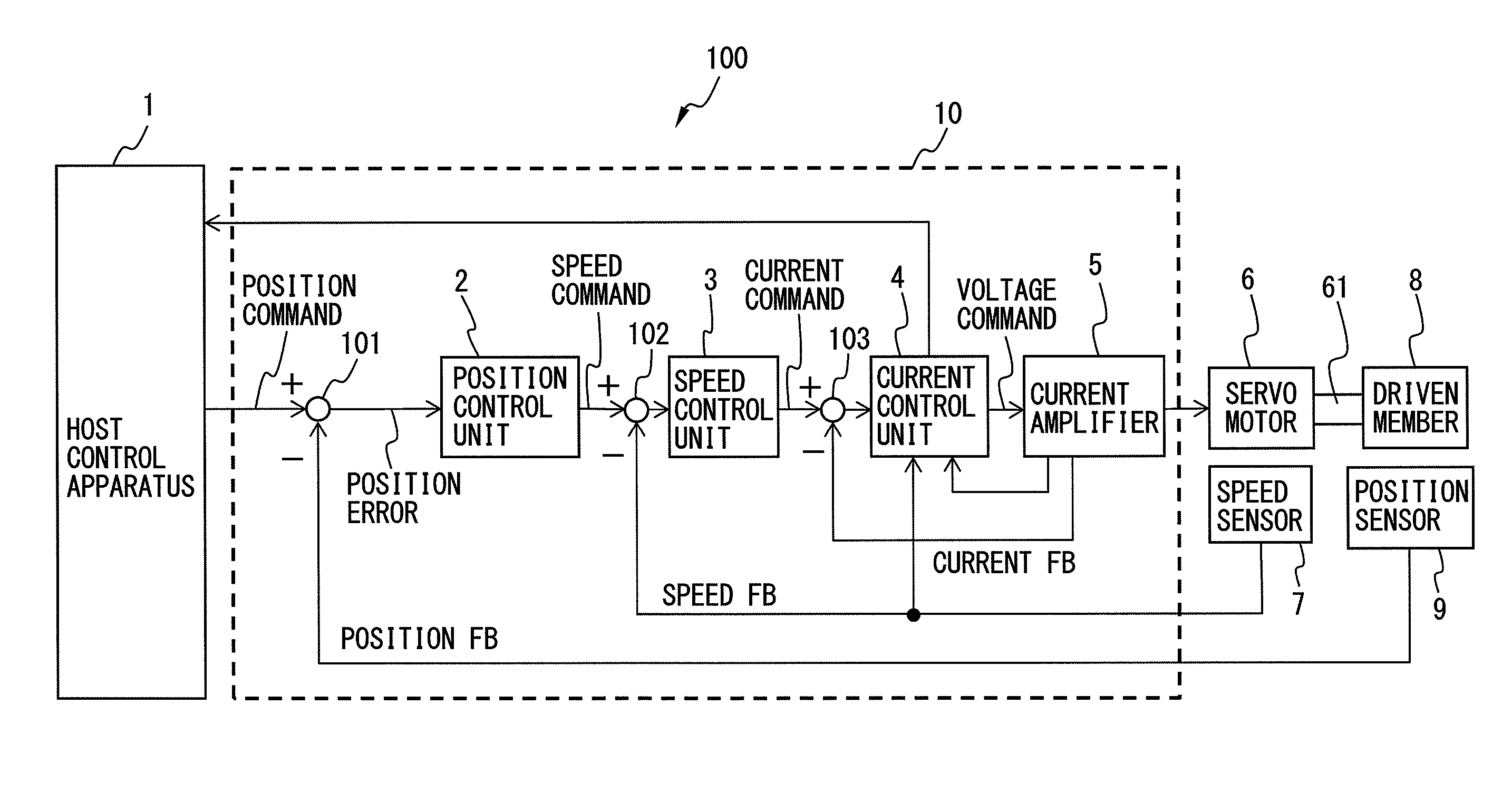
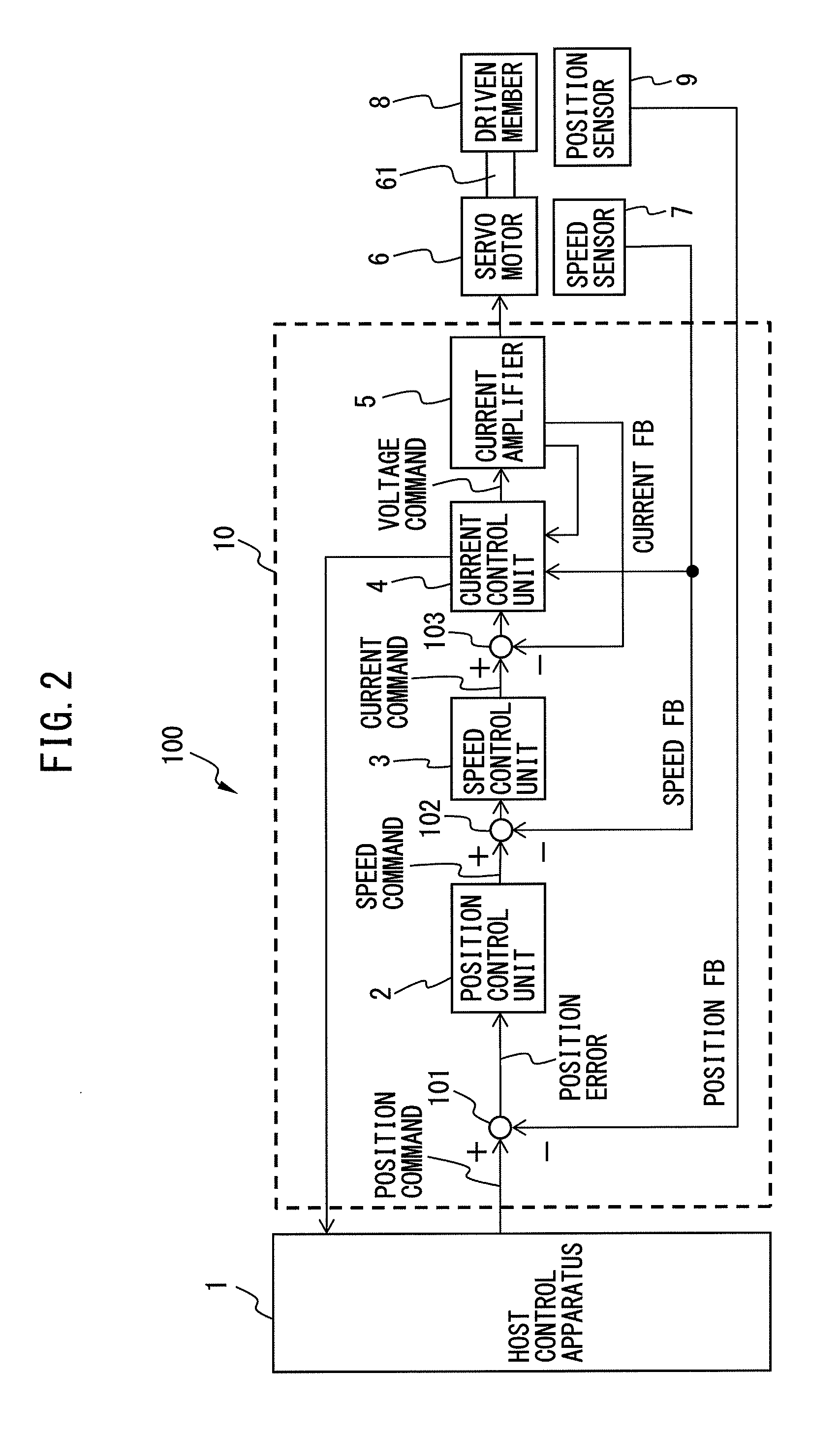
[0034]FIG. 2 shows the configuration of a motor control system 100 according to a first embodiment of the present invention, and FIG. 3 shows in detail the configuration of a current control unit 4 and a current amplifier 5 in a control apparatus 10 constituting the motor control system 100. The motor control system 100 of the present invention comprises the control apparatus 10 which controls a motor, and a host control apparatus 1 which provides a command to the control apparatus 10. The control apparatus 10 includes a position control unit 2 which controls position based on a position command and commanded speed provided from the host control apparatus 1, a speed control unit 3 which controls speed based on a speed command supplied from the position control unit 2, a current control unit 4 which controls current based on a current command supplied from the speed control unit 3, and a current amplifier 5 which amplifies current for driving a driven member 8, or the motor, based on...

embodiment 2

[0090]Next, a motor control system according to a second embodiment will be described. The motor control system according to the second embodiment is characterized in that the host control apparatus includes a saturation flag output unit which, based on the result of the determination made by the voltage saturation processing unit, outputs a saturation flag when the voltage command has exceeded the supply voltage. FIG. 14 is a diagram showing the configuration of the motor control system 200 according to the second embodiment. The same component elements as those in the motor control system 100 of the first embodiment are designated by the same reference numerals, and the details of such component elements will not be further described herein. As shown in FIG. 14, the motor control system 200 according to the second embodiment is characterized in that the host control apparatus 1 includes the saturation flag output unit 20 which, based on the result of the determination made by the ...

embodiment 3

[0092]The first embodiment has shown that the voltage saturation can be avoided by reducing the C-axis speed, i.e., the feed speed, from 120 [mm / sec] to 100 [mm / sec], as shown in FIGS. 9A and 9B to 13A and 13B. The reduced feed speed here is constant irrespective of the angle θ. As a result, the overall work time increases because the feed speed is reduced uniformly over the entire range of angles including the angle of 180° at which the X-axis speed, X-axis acceleration, etc. increase.

[0093]By contrast, a motor control system according to a third embodiment is characterized in that when the voltage command has exceeded the supply voltage, the host control apparatus 1, based on the result of the determination made by the voltage saturation processing unit 41, performs control so that the voltage command does not exceed the supply voltage by reducing at least one of the commanded speed, commanded acceleration, and commanded jerk only for a predetermined region where the voltage comma...


PUM


Abstract

A motor control system comprises a plurality of control apparatuses and a host control apparatus, wherein each of the control apparatuses include a position control unit controlling position based on a position command and commanded speed from the host control apparatus, a speed control unit controlling speed based on a speed command from the position control unit, a current control unit controlling current based on a current command from the speed control unit, and a current amplifier which amplifies motor driving current based on a voltage command from the current control unit, and wherein the current control unit includes a voltage saturation processing unit which determines whether the voltage command has exceeded supply voltage of the current amplifier, and which outputs the result of the determination, and a voltage saturation notifying unit which notifies the host control apparatus of the result of the determination made by the voltage saturation processing unit.

Description

CROSS-REFERENCE TO RELATED APPLICATIONS[0001]This application is a new U.S. patent application that claims benefit of JP 2013-056600, filed on Mar. 19, 2013, the entire content of JP 2013-056600 is hereby incorporated by reference.FIELD OF THE INVENTION[0002]The present invention relates to a motor control system, and more particularly to a motor control system that can detect voltage saturation occurring in a current amplifier used for driving a motor and can notify a host control apparatus accordingly.BACKGROUND OF THE INVENTION[0003]In a system such as a machine tool that is driven using a synchronous motor, if the commanded acceleration is large, the maximum torque of the synchronous motor may be exceeded and the motor may become unable to be operated as commanded. Similarly, depending on the inductance of the synchronous motor, if the commanded jerk is large, the commanded voltage of the synchronous motor may exceed the maximum voltage of a current amplifier and the motor may b...

Claims


Application Information

Patent Timeline
Patent Type & Authority Patents(United States)
IPC IPC(8): H02H7/09G05D13/62H02P21/00G05B19/18H02P21/22H02P23/16H02P23/18H02P25/022H02P27/04H02P27/08H02P29/00H02P29/40
CPCG05D13/62G05B19/404G05B2219/41408G05B2219/43065
Inventor MAEDA, KAZUOMI
Owner FANUC LTD
Why Eureka
Try Eureka