Phase modulation apparatus

a phase modulation and apparatus technology, applied in the direction of electrical apparatus, instruments, optics, etc., can solve the problems of significant deterioration of transmission characteristics, waveform becomes distorted, transmission characteristics are significantly deteriorated, etc., and achieve the effect of simplifying the phase control circuit and miniaturizing the phase modulation apparatus

Active Publication Date: 2015-09-01
NIPPON TELEGRAPH & TELEPHONE CORP
View PDF3 Cites 3 Cited by
  • Summary
  • Abstract
  • Description
  • Claims
  • Application Information

AI Technical Summary

Benefits of technology

[0019]Meanwhile, in the phase control circuit of a phase modulation apparatus according to the disclosure, a single pilot signal is used, and the pilot signal superimposition performed by the pilot signal supplying portion, the synchronous detection performed by the synchronous detecting portion, and the adjustment operation performed by the adjustment portion may be performed in a time-division manner. In the phase modulation apparatus, skew is alternately adjusted by the two phase shifters with a single pilot signal. Since the phase control circuit can be simplified, the phase modulation apparatus can be miniaturized.
[0020]This disclosure can provide a phase modulation apparatus in which each component part is not required to be the same length in the assembling and skew adjustment is easily performed even if temperature characteristics of parts and the change with time occur.

Problems solved by technology

As seen from above, it is obvious in the RZ-QPSK generation, there is a problem that the timings of three kinds of signals including two data sequences (LN1′, LN2) and the clock CLK are aligned in parallel.
However, when skew occurs, a notch and an RZ modulation clock interfere to remove a pulse, so that the output waveform becomes a distorted pulse as shown in FIG. 4B.
Such distortion becomes lack of information to lead to significant deterioration of transmission characteristics.
Thus, as shown in FIG. 5B, the phase confirmation region is narrowed, and even if the clock phase is corresponded to the optimum timing, the interference with the phase transition region cannot be avoided, so that the transmission characteristics are significantly deteriorated.
However, it is impossible to correspond to the delay variation due to temperature and power supply variation and variation in a long term only by initial adjustment, and such correction that operation is always performed at an optimum operating point is required.

Method used


Image

  • Phase modulation apparatus
  • Phase modulation apparatus
  • Phase modulation apparatus

Examples


first embodiment

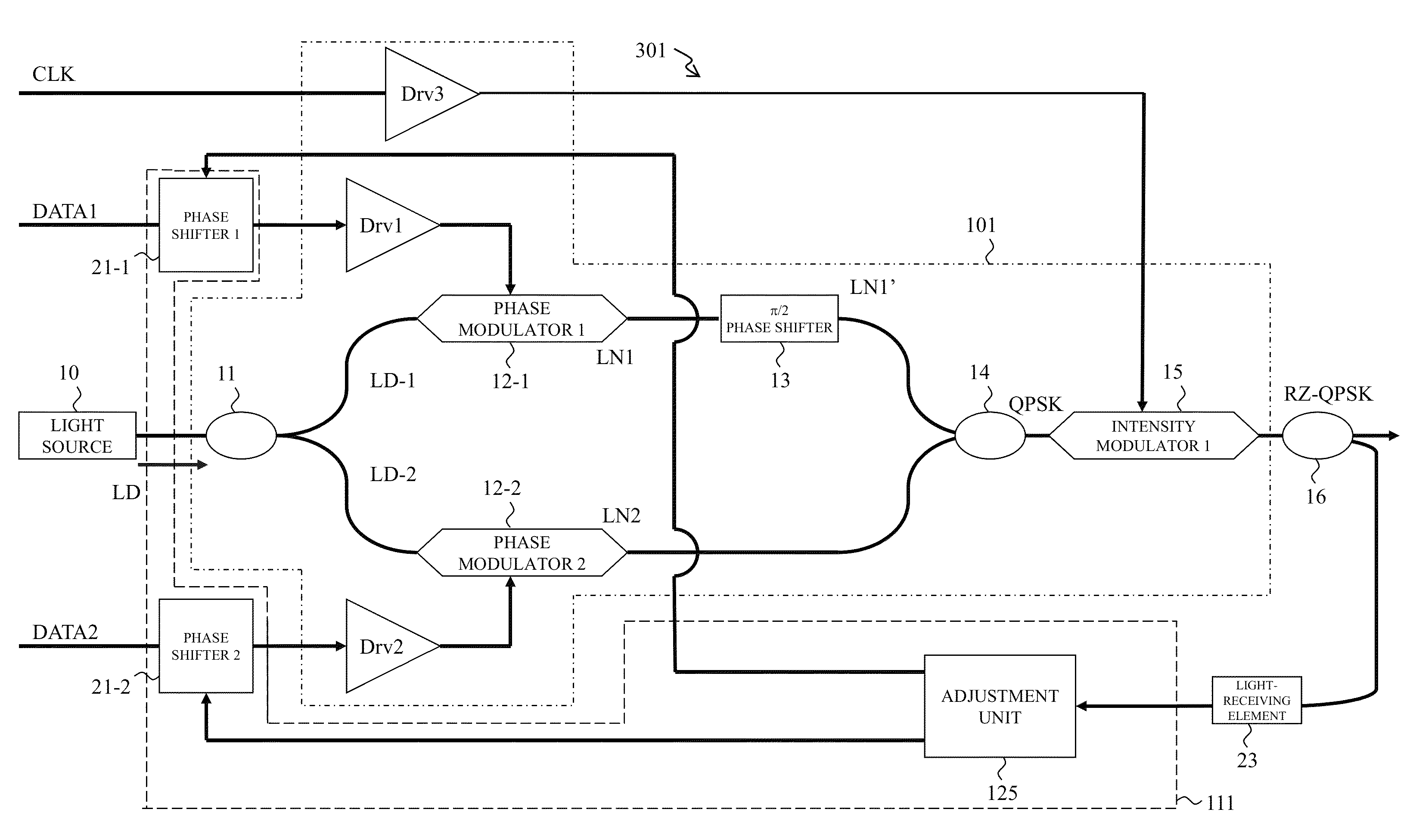
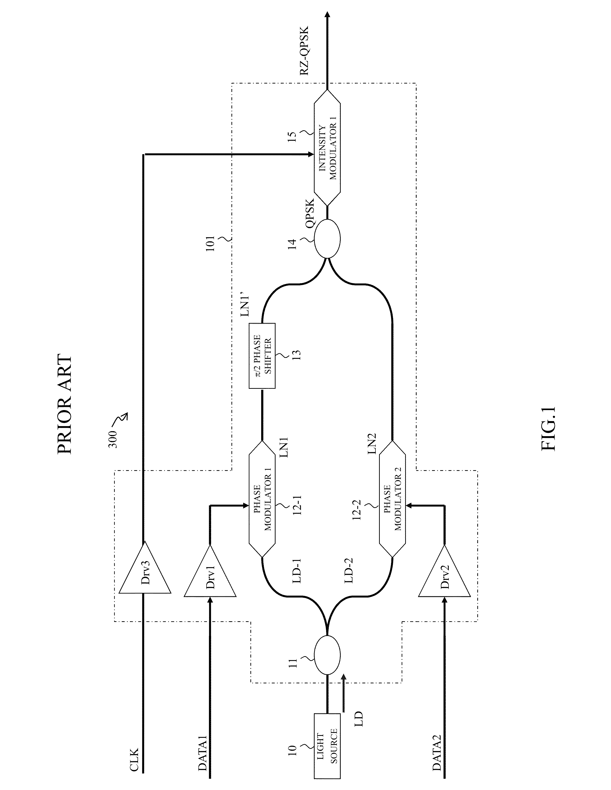
[0034]FIG. 6 is a view for explaining a phase modulation apparatus 301 as an example of the present embodiment. The phase modulation apparatus 301 is provided with an RZ phase modulation circuit 101 and a phase control circuit 111. The RZ phase modulation circuit 101 has a light source 10 outputting continuous light and two phase modulators (12-1, 12-2) and an intensity modulator 15. The phase modulators (12-1, 12-2) phase-modulates the continuous light from the light source 10 based on data signals (DATA1, DATA2) input to each phase modulators and generate two phase modulation optical signals. A phase shifter 13 shifts one phase of the phase modulation optical signal by π / 2 and generates a quadrature phase modulation signal combined with the other phase modulation optical signal. An intensity modulator 15 intensity-modulates the quadrature phase modulation signal with a clock signal CLK synchronized with the data signal to convert the signal into an RZ signal, and, thus, to output ...

second embodiment

[0039]FIG. 9 is a view for explaining a phase modulation apparatus 302 as an example of the present embodiment. The phase modulation apparatus 302 mounts an example of a configuration of the adjustment unit 125 described in the phase modulation apparatus 301 of FIG. 6.

[0040]A phase control circuit 111 has a pilot signal supplying portion 22 which performs pilot signal superimposition in which a pilot signal having a predetermined frequency is superimposed on a control signal J indicating the phase shift amount in which phase shifters (21-1, 21-2) shift the phase of a data signal and the phase shift amount is oscillated with a predetermined frequency, a synchronous detecting portion 24 which performs synchronous detection of an electrical signal, to which the output of the intensity modulator 15 is optical-electrically converted, with the same frequency as the pilot signal, and an adjustment portion 25 which performs adjustment operation in which the control signal J of the phase shi...

third embodiment

[0051]FIG. 12 is a view for explaining a phase modulation apparatus 303 of the second embodiment. The phase modulation apparatus 303 is different from the phase modulation apparatus 302 of FIG. 9 in that a phase control circuit 112 is provided instead of the phase control circuit 111. The phase control circuit 112 and the phase control circuit 111 are different in the number of the pilot signals. The phase modulation apparatus 303 performs the skew adjustment with a single pilot signal having a frequency f. More specifically, the skew adjustment of the phase modulation optical signal LN1 and the skew adjustment of the phase modulation optical signal LN2 are performed while shifting the time. Thus, the phase modulation apparatus 303 has in the phase control circuit 112 a switching switch 26 switching the output destination of the pilot signal. The skew adjustment method is similar to the skew adjustment method in the phase modulation apparatus 302 described in FIGS. 10 and 11.


PUM

PropertyMeasurementUnit
optical phasesaaaaaaaaaa
optical phaseaaaaaaaaaa
Phaseaaaaaaaaaa

Abstract

A phase modulation apparatus has a light source outputting continuous light, two phase modulators, and an intensity modulator. The phase modulation apparatus is provided with an RZ phase modulation circuit, in which the phase modulators phase-modulate the continuous light from the light source with data signals input to the phase modulators and generate two phase modulation optical signals, a phase shifter shifts the phase of one phase modulation optical signal by π / 2, and an intensity modulator intensity-modulates a multiplexed signal, combined with the other phase modulation optical signal, with an input clock signal CLK to convert the signal into an RZ signal, and, thus, to output the RZ signal, and a phase control circuit which adjusts the phases of the phase modulation optical signals generated by the phase modulator of the RZ phase modulation circuit so that the output of the RZ phase modulation circuit is maximum.

Description

BACKGROUND[0001]1. Field of the Disclosure[0002]The present disclosure relates to a phase modulation apparatus which modulates a phase of light in a digital signal sequence.[0003]2. Discussion of the Background Art[0004]As a method of modulating light with a digital signal, Quadrature Phase Shift Keying (QPSK) and Differential Quadrature Phase Shift Keying (DQPSK) have been known (for example, see Patent Document 1).[0005]In a long-haul transmission system, in order to suppress interference between codes and to realize the high sensitivity, a QPSK modulated or DQPSK modulated optical signal is sometimes further subjected to RZ (Return to Zero) intensity modulation. FIG. 1 is a view for explaining a phase modulation apparatus 300 employing an RZ-QPSK modulation method. The RZ-QPSK modulation is performed by the following procedure.(1) Continuous light LD of a light source 10 is branched by a 1:2 coupler 11.(2) Phase modulators (12-1, 12-2), based on the digital input signal (DATA1, D...

Claims


Application Information

Patent Timeline
Patent Type & Authority Patents(United States)
IPC IPC(8): G02F1/01H04B10/50G02F1/225H04B10/556G02F1/21
CPCG02F1/01G02F1/0123G02F1/225H04B10/5053H04B10/50577H04B10/5561G02F2001/212G02F2203/21H04B2210/517G02F1/212
Inventor ONO, SHIGERUOGIHARA, KOUICHIENDO, JUNYONEYAMA, MIKIO
Owner NIPPON TELEGRAPH & TELEPHONE CORP
Why Eureka
Try Eureka