Reinforced masonry panel structures

a technology of reinforced masonry and panel structure, applied in the direction of structural elements, building components, branching pipes, etc., to achieve the effect of reducing or eliminating differential horizontal movement, preventing excessive lateral movement of masonry, and withstanding higher lateral loads

Active Publication Date: 2015-09-08
WEMBLEY INNOVATION
View PDF30 Cites 5 Cited by
  • Summary
  • Abstract
  • Description
  • Claims
  • Application Information

AI Technical Summary

Benefits of technology

[0023]The reinforcing bar may be a snug sliding fit in the socket (e.g. there may be a total radial clearance of 1 mm or less for a rebar of 16 mm diameter). This allows relative longitudinal movement to take place between the reinforcing bar and the socket, thereby accommodating differential expansion between the masonry infill and the load bearing structure. Suitable seals or sealant may be applied to prevent the wet concrete from entering the socket as the bond beam is cast. Under transverse loading of the masonry, the reinforcing bar ends engage the interior sides of the sockets and transfer the transverse loads to the load bearing structure. Under such loading, the bond beam and reinforcing bars will tend to bow. Reaction forces from the sockets at the bar ends and the stiffness of the bond beam and surrounding masonry tend to restrain and prevent excessive lateral movement of ...

Problems solved by technology

This form of construction, while effective, brings with it the following disadvantages:1. An expa...

Method used


Image

  • Reinforced masonry panel structures
  • Reinforced masonry panel structures
  • Reinforced masonry panel structures

Examples


Embodiment Construction

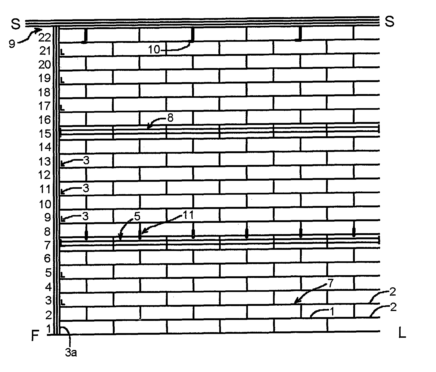
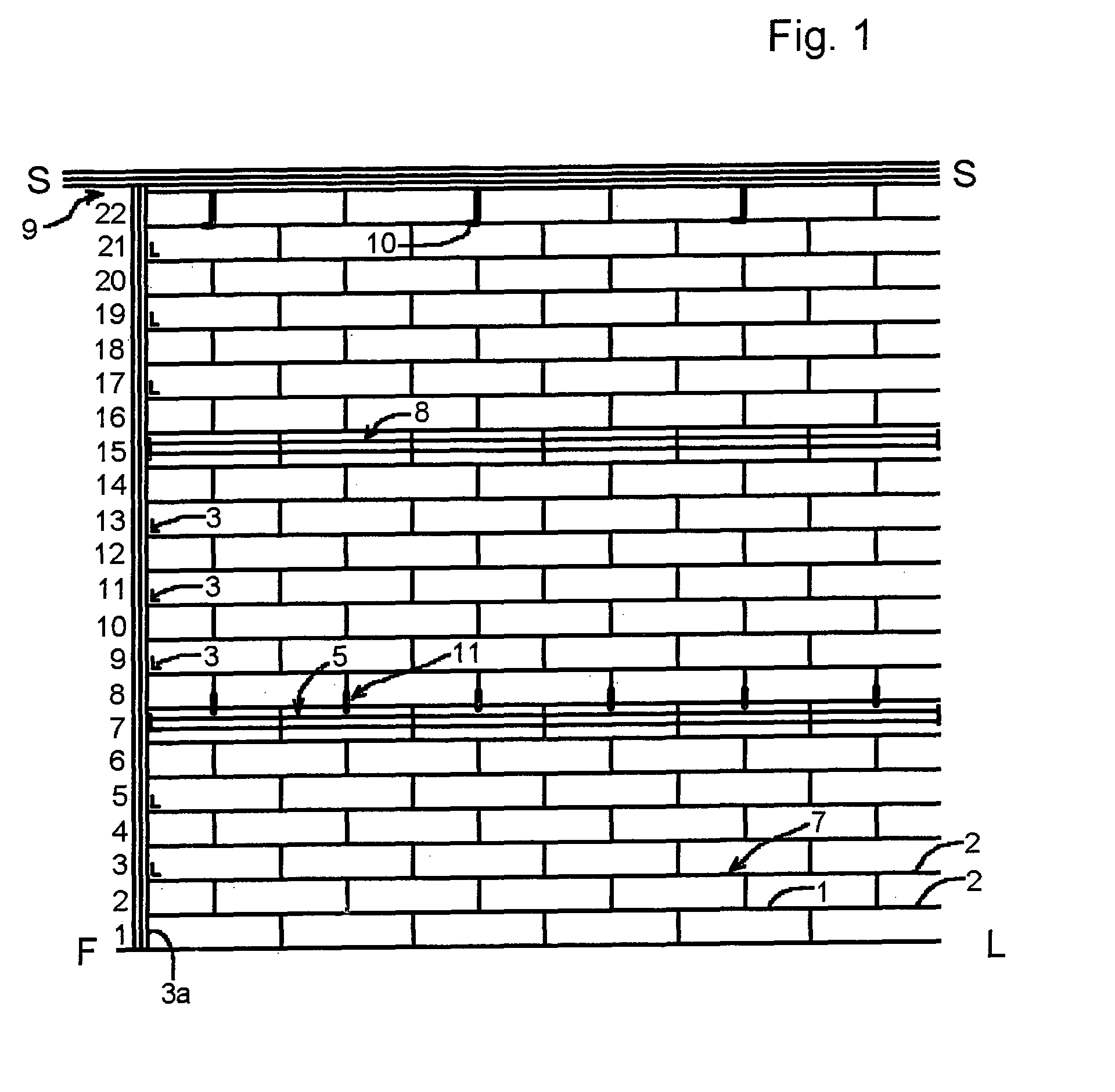
[0054]The infill wall section diagrammatically shown in FIG. 1 consists of 22 courses of blocks (labelled from floor level FL to soffit SS 1-22) laid with standard 10 mm mortar joints and incorporating two vertically spaced bond beams. The materials specification for the wall is:[0055]1. Aquaguard® D.P.C. to first course.[0056]2. Bed joint reinforcement every course (at 225 mm centres) BRC 3.5 mm galvanised.[0057]3. 175 mm Ancon® frame ties at 450 mm centres to vertical end steels 3a. [0058]4. 12 mm thick×140 mm wide, Corofil® expansion joint strip at junction of steel and blockwork vertically.[0059]5. Seventh course bond beam:[0060]Hollow block exterior dimensions (in mm, to match other blocks in wall): 140 W×215 D×440 L[0061]Hollow section interior dimensions (each block, in mm): 80 W×167 D×440 L. This provides sufficient strength to the resulting bond beam, and sufficient concrete cover for corrosion protection of the rebars, as may be required by local building regulations and s...


PUM


Abstract

A method of constructing a masonry infill in a load bearing structure comprises the steps of: laying one or more courses of masonry (7) in the infill space; partitioning off a casting space having as its base the then uppermost course of masonry (22); the casting space extending from one side of the infill space to the other; positioning reinforcing material (14) in the casting space; securing an end of the reinforcing material to the load bearing structure; filling the casting space with concrete (20), and laying one or more further courses of masonry on top of the filled casting space. The reinforced concrete forms a bond beam which strengthens the masonry. The reinforcing material may be rebar, secured to a load-bearing frame of the building by a cleat (16) having pockets (12) for reception of the rebar ends. Optionally the reinforcement may be tensioned, to pre-stress the bond beam. The bond beam may also be used to strengthen bonded, load-bearing masonry panels in bending, without being secured to an adjacent load-bearing structure.

Description

BACKGROUND[0001]Current techniques for constructing larger buildings usually involve the use of a load bearing frame of steel or reinforced concrete, with attached cladding and / or masonry infills. In the case of masonry walls in such structures and elsewhere, it is necessary to provide additional strengthening where the area of the wall increases beyond certain limits. The strengthening is required to support the weight of the wall; to resist environmental loading such as wind forces, differences in air pressure and earthquakes; as well as to withstand other dynamic service loads such as crowd pressure, vehicle impact or explosions. The required strength for a given structure is governed not only by the laws of physics but also by local building regulations.[0002]Traditionally where additional strength is needed, walls have been supported by cross walls, piers and areas of wall thickening. More recently the standard windpost has been developed, which occurs in most building walls (p...

Claims


Application Information

Patent Timeline
IPC IPC(8): E04B1/16
CPCE04B1/165Y10T403/3933E04B1/4107E04B2/24E04B2002/0254E04C2/041F16B9/052F16B9/056E04B2/20E04B2/64E04B2/68E04H9/02E04H9/021
Inventor CLEAR, LIAM
Owner WEMBLEY INNOVATION
Why Eureka
Try Eureka