Method for controlling exposure time of high dynamic range image

a high dynamic range, image technology, applied in the direction of color television details, television system details, television systems, etc., can solve the problems of reducing the overall image quality and unable to obtain the best image quality, and achieve optimal exposure duratio, best image quality, and optimal exposure duratio

Active Publication Date: 2015-09-08
QUANTA COMPUTER INC
View PDF19 Cites 4 Cited by
  • Summary
  • Abstract
  • Description
  • Claims
  • Application Information

AI Technical Summary

Benefits of technology

[0009]In summation of the above, an image sensor is utilized in the method for controlling exposure time of high dynamic range images of the present invention to consecutively generate a plurality of high dynamic range images in the image generation process and perform image quality evaluations for the high dynamic range images. The search for the optimal exposure duration ratio begins with the lowest exposure duration ratio, the exposure duration ratio is step by step increased till the image quality begins to deteriorate, and then the previous exposure duration ratio may be decided as the optimal exposure duration ratio. When the optimal exposure duration ratio is obtained, the method for an image quality evaluation is applied to verify if the image quality of the present image is the same as the image quality of the previous image. If both image qualities are the same, the optimal exposure ratio will be preserved; if the image quality deteriorates due to variation of the light source, the original lowest exposure duration ratio will be reset as the exposure duration ratio and the search for the optimal exposure duration ratio is repeated.

Problems solved by technology

Since the dynamic range of a screen is very low and about 200, the compression process of color mapping will destroy details and contrast of an image and cause the overall image quality to downgrade.
In other words, best image quality cannot be obtained by simply increasing the exposure duration ratio.

Method used


Image

  • Method for controlling exposure time of high dynamic range image
  • Method for controlling exposure time of high dynamic range image
  • Method for controlling exposure time of high dynamic range image

Examples


Embodiment Construction

[0014]To illustrate the characteristics, content, and advantages of the present invention and the effects it can fulfill, a preferred embodiment and the corresponding drawings are provided to offer more detailed descriptions. The purpose of the drawings being used is for illustration and to assist the specifications, they are not necessarily the real proportion and precise allocations of the embodiments of the present invention. Thus, they should not be used to limit the privilege coverage of the practical embodiments of the present invention.

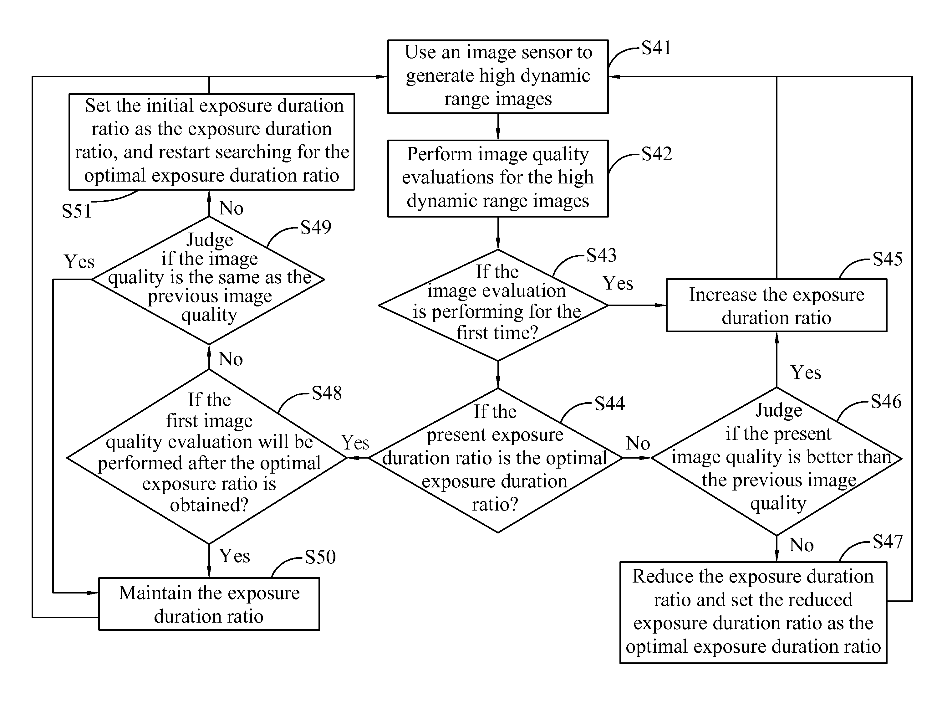
[0015]FIG. 1 is a flow diagram showing the method for controlling exposure time of high dynamic range images according to a preferred embodiment of the present invention. The flow of FIG. 1 includes steps of:

[0016]S41: Use an image sensor to generate high dynamic range images.

[0017]S42: Perform image quality evaluations for the high dynamic range images.

[0018]S43: If the image evaluation is performed for the first time? If yes, then enter Step ...


PUM


Abstract

A method for controlling an exposure duration of a high dynamic range image, including: consecutively generating a first high dynamic range image having a first exposure duration ratio and a second high dynamic range image having a second exposure duration ratio greater than the first exposure duration ratio; performing image quality evaluations on both the first high dynamic range image and the second high dynamic range image to obtain a first image quality and a second image quality, respectively; and determining whether the second image quality is better than the first image quality; if yes, generating a third high dynamic range image having a third exposure duration ratio greater than the second exposure duration ratio; if not, generating the third high dynamic range image having the first exposure duration ratio and setting the first exposure duration ration as the optimal exposure duration ratio.

Description

CROSS-REFERENCE TO RELATED APPLICATION[0001]This application claims priority from Taiwan Patent Application No. 102128455, filed on Aug. 8, 2013 in Taiwan Intellectual Property Office, the contents of which are hereby incorporated by reference in their entirety.BACKGROUND OF THE INVENTION[0002]1. Field of the Invention[0003]The present invention is related to a method for controlling exposure time of high dynamic range images, and particularly related to a method of using an image sensor to capture images of different exposure durations, merging images of different exposure durations to form a high dynamic range image, and adjusting an exposure duration ratio to obtain a high dynamic range image of best quality.[0004]2. Description of the Related Art[0005]The dynamic range of a contemporary consumer digital camera or webcam, which is the ratio between the greatest to the smallest brightness values, is around 400, and the dynamic ranges of more professional single-eye cameras can be ...

Claims


Application Information

Patent Timeline
Patent Type & Authority Patents(United States)
IPC IPC(8): H04N5/235H04N5/355
CPCH04N5/2353H04N5/2356H04N5/355H04N5/35536H04N5/2355H04N23/73H04N23/741H04N25/589H04N23/743H04N25/57H04N25/58
Inventor LIN, KENG-SHENGCHENG, CHIH-CHILI, CHUNG-TECHEN, HSIN-YUYANG, WEN-CHU
Owner QUANTA COMPUTER INC
Why Eureka
Try Eureka