
Finger joint prosthesis

a finger joint and prosthesis technology, applied in the field of finger joint prosthesis, can solve the problems of pain, pain, and even elimination of joint function, and achieve the effects of easy implantation, reduced pain, and improved stability

Inactive Publication Date: 2015-09-22
WALDEMAR LINK GMBH & CO
View PDF17 Cites 0 Cited by
  • Summary
  • Abstract
  • Description
  • Claims
  • Application Information

AI Technical Summary

Benefits of technology

The technical effect of this patent is to develop a finger joint prosthesis that is stable and easy to implant, with the unique design of a hollow body that allows for relative movement between the first and second joint elements, as well as a spindle that connects to the hollow body for rotation. The hollow bodies have the advantage of increased geometrical moments of inertia in relation to torsion and flexing, resulting in improved stability and fatigue strength. The external and internal hollow bodies can be made from metal, with titanium nitrite being particularly preferable due to its excellent properties. To reduce frictional forces between the hollow bodies, plastic discs or washers can be fitted between their end faces.

Problems solved by technology

In that case, the disease leads to “wear” of the joint cartilage and consequently corresponding inappropriate strains and pressures with complete changes in the joint surfaces, which result in painful restriction on or even elimination of the joint function.
On the other hand, functional troubles with the finger middle joints can, however, also occur as a result of an injury, for example due to luxation of the joint or due to a joint fracture.
Primary treatment of a joint fracture generally results in what is referred to as “post-traumatic arthrosis” of the joint, which also leads to a painful restriction in function or elimination of function of the finger middle joint.
As the finger middle joint had to be luxated laterally in the procedure for implantation of the known finger joint prostheses, the extensor tendon system, the two flexor tendons and the lateral ligaments of the joint were irritated, which resulted in operability being later adversely affected.
In the method described in EP 1 096 906 the finger joint prosthesis could be implanted in the assembled condition radially into a previously produced bore in the finger joint, which represents a marked simplification in installation and results in slight injuries to the finger.
On the other hand, that finger joint prosthesis is of an excessively filigree structure and suffers from a lack of strength and durability.

Method used


Image

  • Finger joint prosthesis
  • Finger joint prosthesis

Examples


Embodiment Construction

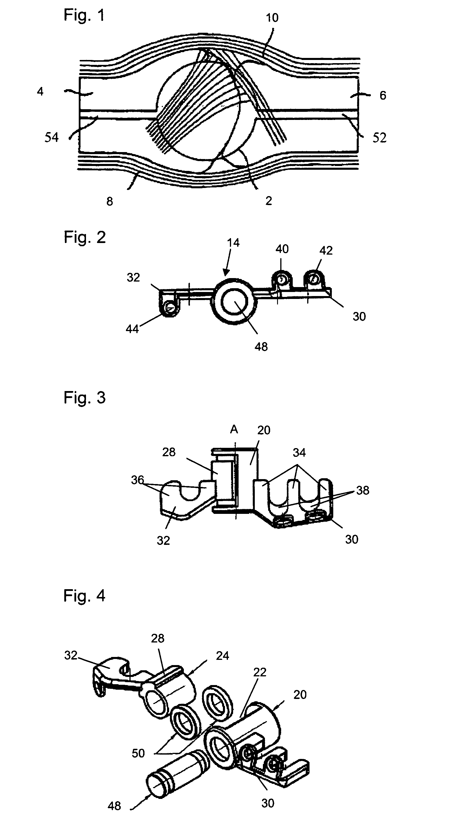
[0028]FIG. 1 shows the radial side of a finger middle joint 2 with the proximal phalanx 4, that is which is towards the body, and the distal phalanx 6, that is which is remote from the body. The extensor tendon 8 is shown underneath the phalanx and the flexor tendon 10 is shown above the middle phalanx.

[0029]The finger joint prosthesis shown in FIGS. 2 to 4 serves for radial implantation in the finger joint shown in FIG. 1 at the location of the hinge joint which is indicated in FIG. 1 by the circle at the center.

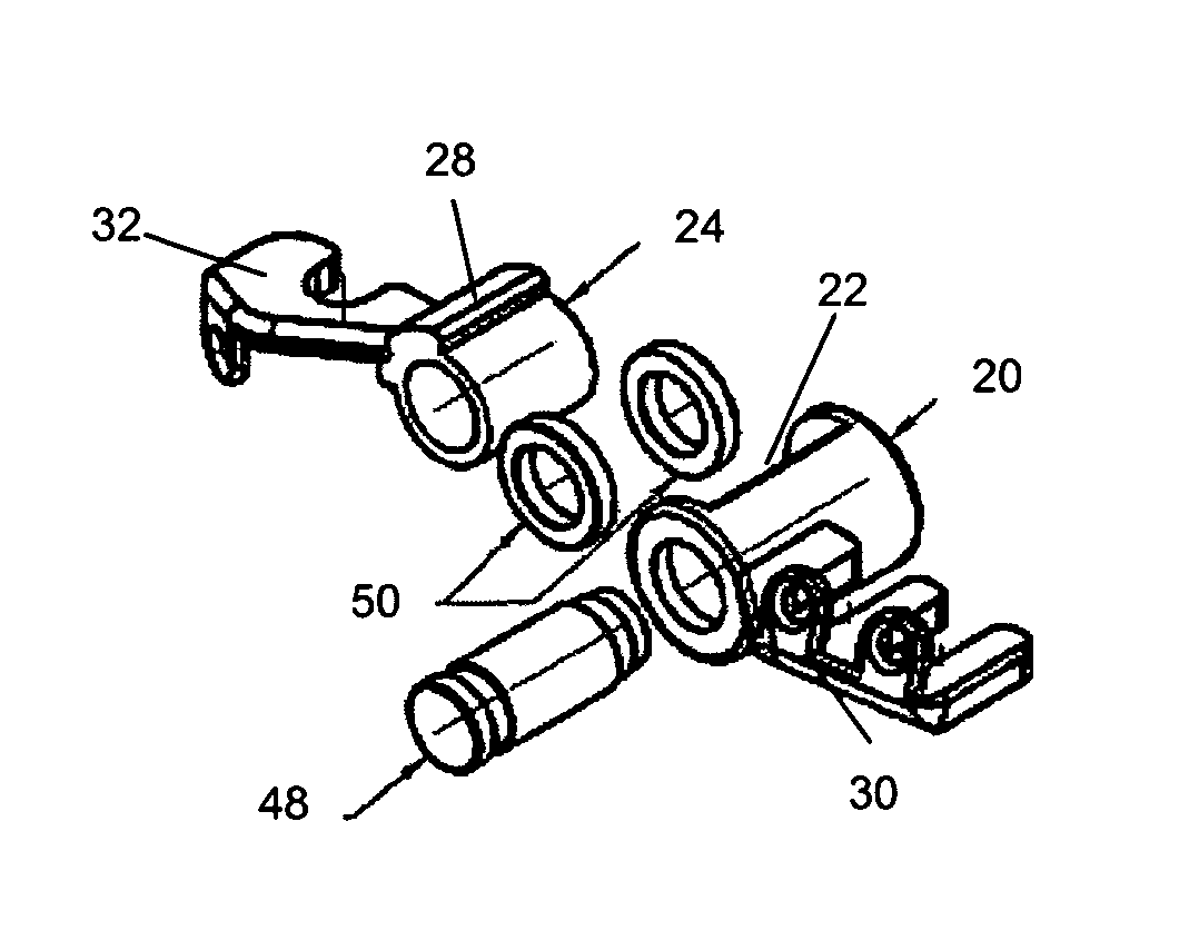
[0030]FIG. 2 shows a side view of the assembled finger joint prosthesis. It comprises a joint body 14 including a first joint element and a second joint element, which are hingedly connected in such a way that the second joint element is pivotable with respect to the first joint element about a vertical axis A shown in FIG. 3.

[0031]FIGS. 2 and 3 show a side view and a plan view of the finger joint prosthesis in the implantation position. As best seen in the exploded view of...


PUM

PropertyMeasurementUnit
angleaaaaaaaaaa
diameteraaaaaaaaaa
diameteraaaaaaaaaa

Abstract

A finger joint prosthesis is provided including a joint body having first and second joint elements, which are connected together pivotably about a rotary axis and from each of which extends an anchoring bar for fixing to a proximal and / or distal phalanx. The anchoring bars have eyes with openings for receiving fixing screws. To increase stability, it is proposed that the first joint element have an external hollow body with an insertion opening, that the second joint element have an internal hollow body, and that the internal hollow body in the position of installation can be inserted by way of the insertion opening relatively movably into the external hollow body. A spindle can be inserted in the position of installation into the internal hollow body for rotationally movable connection to the external hollow body.

Description

CROSS-REFERENCE TO RELATED APPLICATIONS[0001]This application is a Section 371 of International Application No. PCT / EP2008 / 001359, filed Feb. 21, 2008, which was published in the English language on Aug. 28, 2008, under International Publication No. WO 2008 / 101696 A2 and the disclosure of which is incorporated herein by reference.BACKGROUND OF THE INVENTION[0002]The invention concerns a finger joint prosthesis comprising a joint body having first and second joint elements. The joint elements are connected together pivotably about a rotary axis, and extending from each joint element is an elongate anchoring bar for fixing to a proximal and / or distal phalanx. One or more eyes with openings for receiving fixing screws are also provided on the anchoring bars.[0003]Functional troubles with finger middle joints can occur on the one hand by virtue of genetic degenerative disease, joint arthrosis. In that case, the disease leads to “wear” of the joint cartilage and consequently correspondin...

Claims


Application Information

Patent Timeline
Patent Type & Authority Patents(United States)
IPC IPC(8): A61F2/42A61F2/30
CPCA61F2/4241A61F2002/30578A61F2002/30624A61F2002/4248A61F2310/00023A61F2310/00323A61F2310/00796A61F2002/4243
Inventor KELLER, ARNOLDRANFT, CHRISTOPH
Owner WALDEMAR LINK GMBH & CO
Learn More