
Heat pump type clothes dryer with secondary blowing mechanism

a technology of heat pump and dryer, which is applied in drying machines, lighting and heating apparatus, furnaces, etc., can solve the problems of increased noise of fans, increased power consumption, and increased pressure loss of air exhaust lines, so as to reduce the amount of air introduced and increase the internal pressure of the drum

Inactive Publication Date: 2015-09-22
SAMSUNG ELECTRONICS CO LTD
View PDF26 Cites 2 Cited by
  • Summary
  • Abstract
  • Description
  • Claims
  • Application Information

AI Technical Summary

Benefits of technology

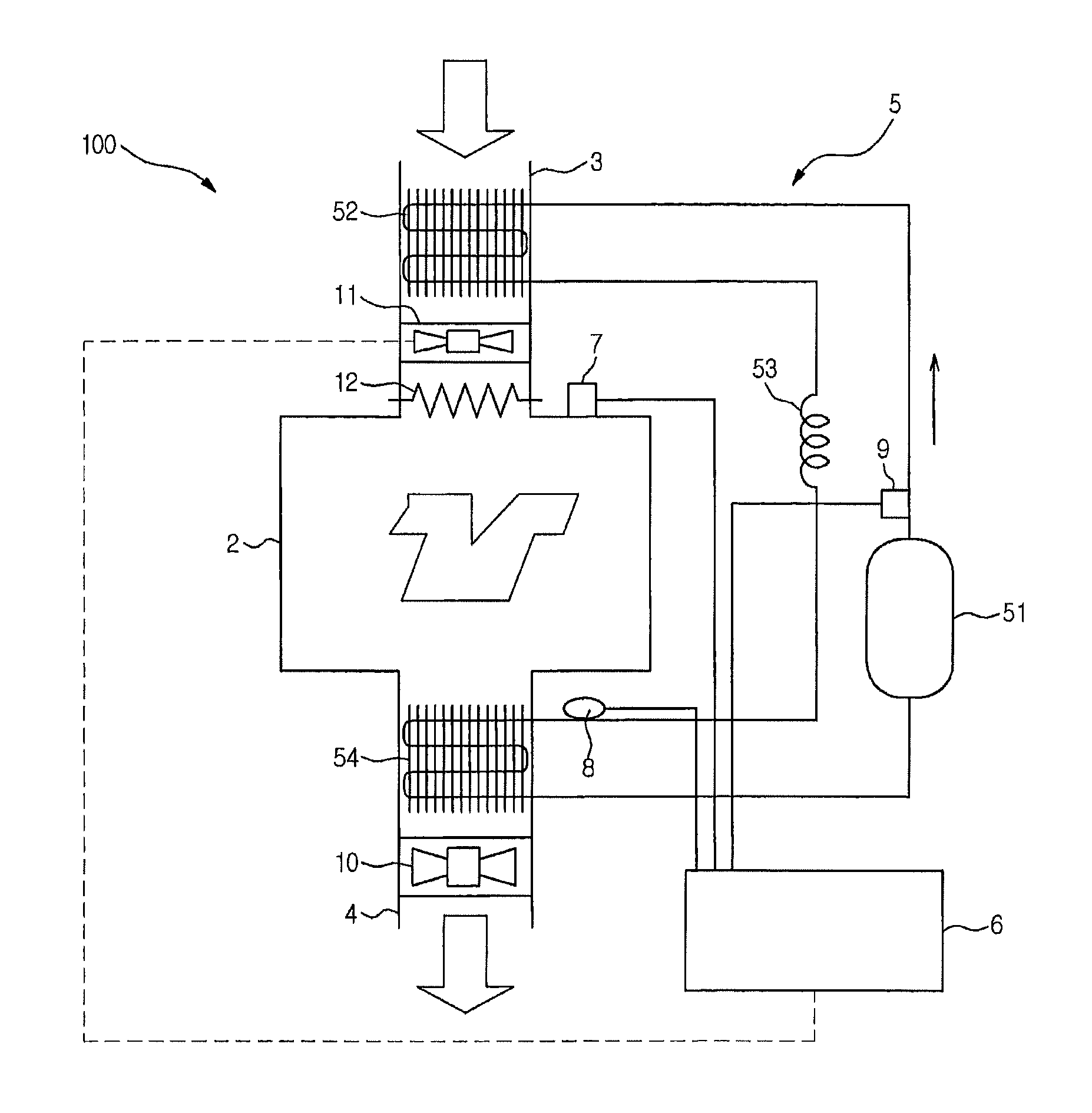
The invention is a heat pump type clothes dryer that solves issues of pressure loss and air flow restrictions to improve drying capacity without increasing power consumption or noise of the fan. It achieves this by compensating for pressure loss caused by a radiator and increasing the flow rate of air passing around the radiator. It also suppresses the introduction of ambient air through gaps formed in air flow lines to prevent degradation in drying capacity. To prevent the heat absorber from being frosted, a refrigerant temperature measurer measures the refrigerant temperature and a controller reduces the air blowing rate of the second blowing mechanism when the refrigerant temperature is not more than a predetermined temperature. To prevent the temperature of the heat pump circuit from being excessively increased, a refrigerant pressure measurer measures the refrigerant pressure and a controller maintains or increases the air blowing rate of the second blowing mechanism when the refrigerant pressure is not less than a predetermined pressure. To prevent frost or unpleasant conditions in an indoor space, a drum pressure measurer measures the internal pressure of the drum and a controller controls the second blowing mechanism such that the internal pressure of the drum is not more than a predetermined pressure.

Problems solved by technology

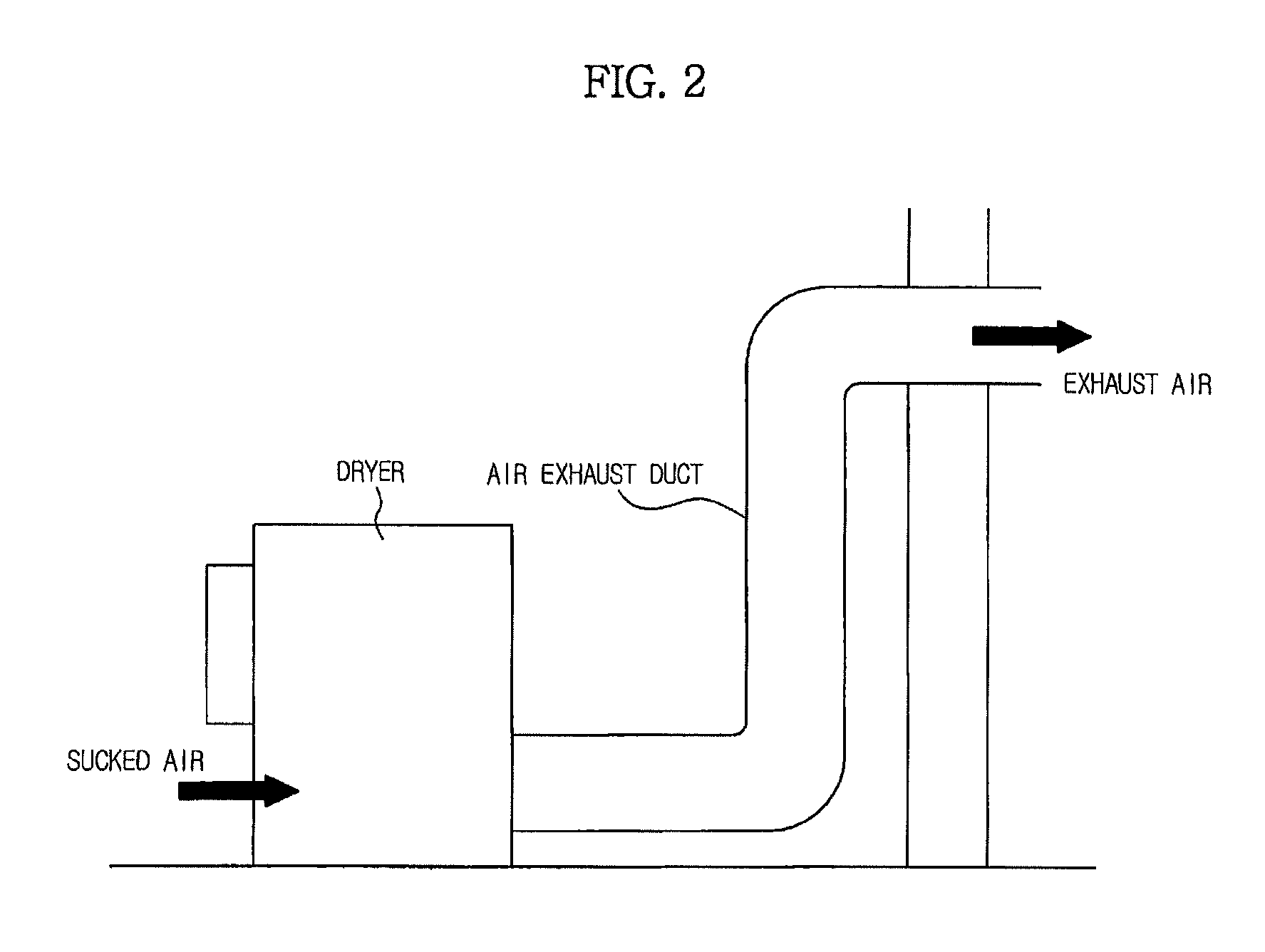
However, when the flow rate of exhaust air increases, the pressure loss of the air exhaust line may also be increased, because an air exhaust duct is connected to the dryer, as shown in FIG. 2.
For this reason, there may be problems such as increased power consumption and increased noise of the fan.
As a result, there may be formation of frost or formation of unpleasant conditions in an indoor space.

Method used


Image

  • Heat pump type clothes dryer with secondary blowing mechanism
  • Heat pump type clothes dryer with secondary blowing mechanism
  • Heat pump type clothes dryer with secondary blowing mechanism

Examples


Embodiment Construction

[0024]Reference will now be made in detail to the embodiments, examples of which are illustrated in the accompanying drawings, wherein like reference numerals refer to like elements throughout. The embodiments are described below by referring to the figures.

[0025]Referring to FIG. 3, a clothes dryer according to an exemplary embodiment is illustrated. The clothes dryer, which is designated by reference numeral 100, uses a suction / exhaust system. As shown in FIG. 3, the clothes dryer 100 includes a drum 2 to accommodate clothes, an air suction or intake line 3 to suck air into the drum 2, an air exhaust line 4 to exhaust air from the drum 2, a heat pump circuit 5, and a controller 6 to control various parts of the clothes dryer 100. A drum pressure sensor 7 is installed in the drum 2. The drum pressure sensor 7 functions as a pressure measurer to measure the internal pressure of the drum 2.

[0026]The heat pump circuit 5 includes a refrigeration cycle in which a compressor 51, a radiat...


PUM


Abstract

A heat pump type clothes dryer compensates for pressure loss caused by a radiator to increase the flow rate of air passing around the radiator, and suppressing introduction of ambient air through gaps formed in air flow lines to avoid degradation in drying capacity, while avoiding an increase in the power consumption or noise of a fan. The clothes dryer includes a drum to accommodate clothes, an air suction or intake line to suck air into the drum, an air exhaust line to exhaust air from the drum, a heat pump circuit including a compressor, a radiator, a pressure reducer, and a heat absorber, where the heat absorber is provided in the air exhaust line, and the radiator is provided in the air suction or intake line, a first blowing mechanism provided in the air exhaust line, and a second blowing mechanism provided in the air suction or intake line.

Description

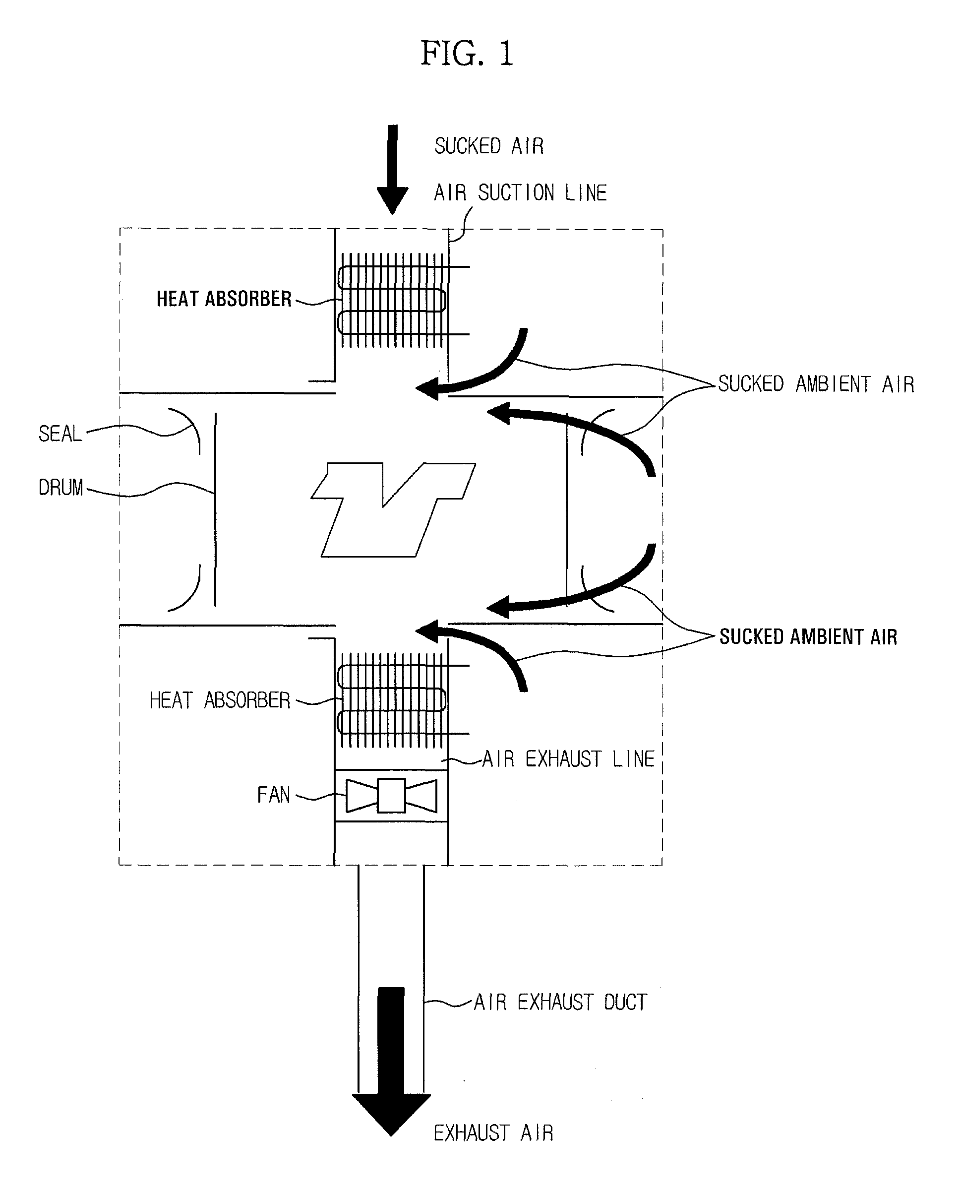
CROSS-REFERENCE TO RELATED APPLICATIONS[0001]This application claims the priority benefit of Japanese Patent Application No. 2010-278379 filed on Dec. 14, 2010 in the Japan Patent Office, the disclosure of which is incorporated herein by reference.BACKGROUND[0002]1. Field[0003]Embodiments relate to a heat pump type clothes dryer.[0004]2. Description of the Related Art[0005]As an example of a conventional clothes dryer, Japanese Unexamined Patent Publication No. 61-22894 discloses a heat pump type dryer (see FIG. 1). In the disclosed heat pump type dryer, a condenser (radiator) is provided at an air suction or intake line, which sucks or intakes air into a drum. Also, a fan and a heat absorber (evaporator) are provided at an air exhaust line, through which air is exhausted from the drum. In accordance with this configuration, the heat pump type dryer recovers exhaust heat from the exhaust air, and heats the sucked or intake air using the recovered heat.[0006]However, in the configura...

Claims


Application Information

Patent Timeline
Patent Type & Authority Patents(United States)
IPC IPC(8): D06F58/28D06F58/20
CPCD06F58/206D06F58/28D06F2058/287D06F2058/2854D06F2058/2864D06F58/26D06F58/34D06F2103/30D06F2103/36D06F2103/50D06F2105/24D06F2105/26D06F2105/28F26B9/02
Inventor WAKIZAKA, EIJI
Owner SAMSUNG ELECTRONICS CO LTD
Learn More