

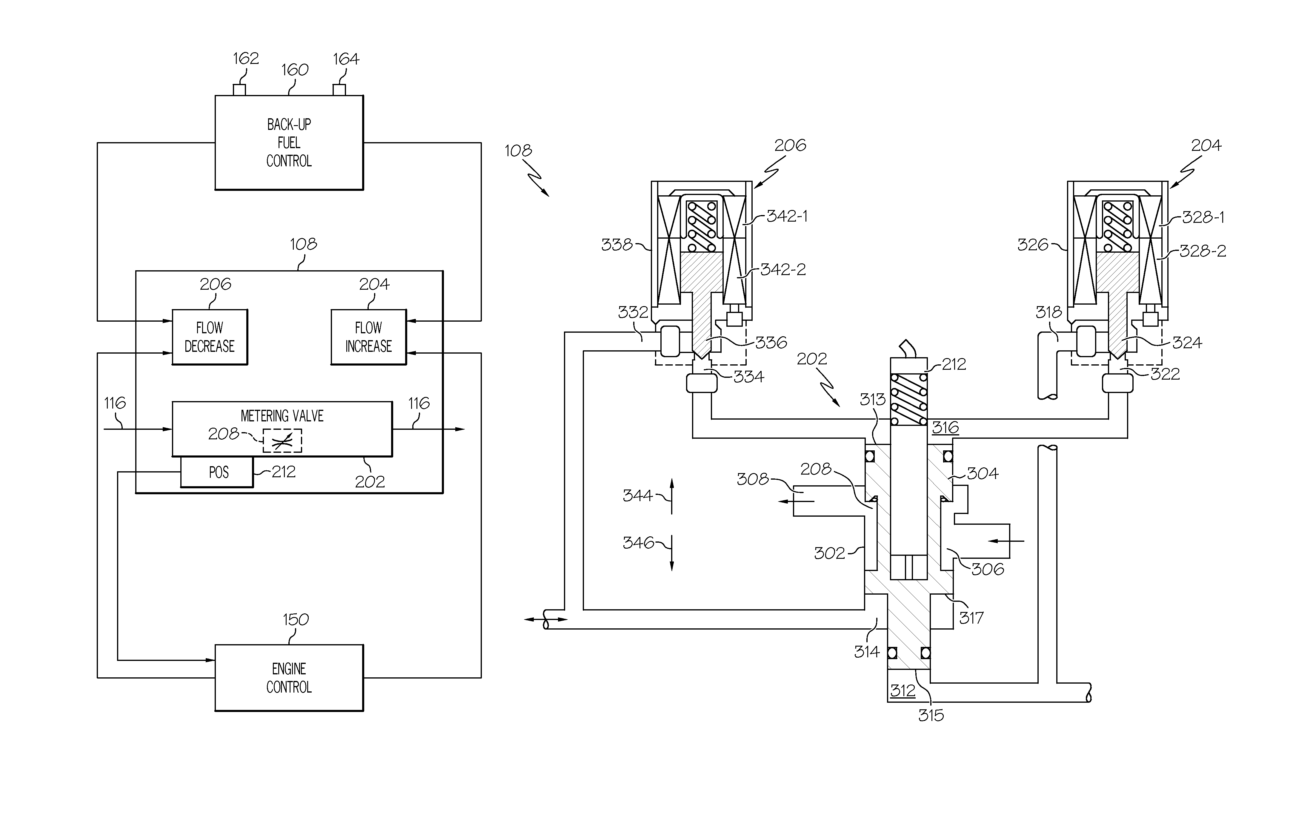
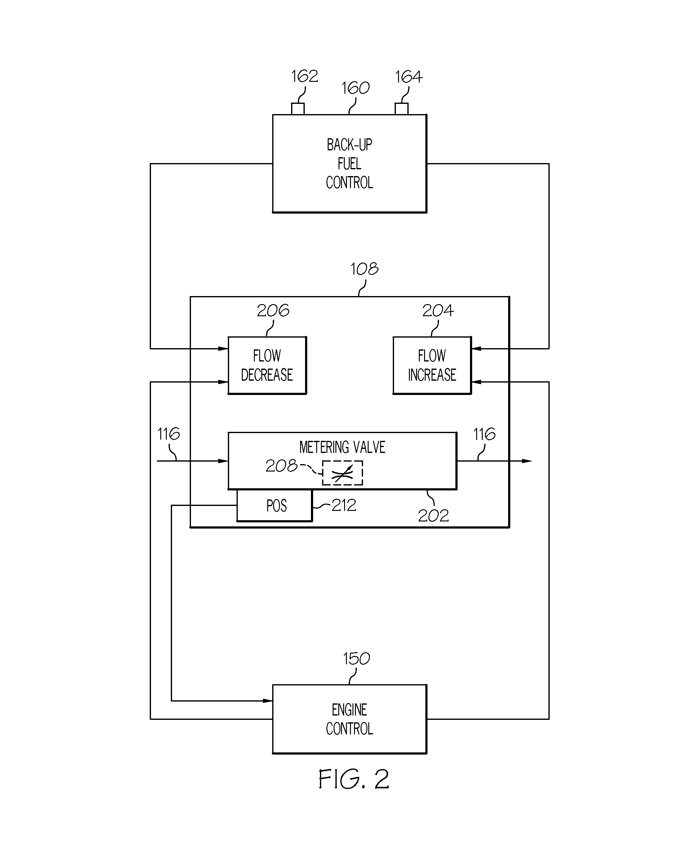
Gas turbine engine fuel metering valve adapted to selectively receive fuel flow increase/decrease commands from the engine control and from the back-up fuel control
a gas turbine engine and fuel metering valve technology, applied in the direction of turbine/propulsion fuel valves, valve operating means/release devices, machines/engines, etc., can solve the problems of power loss, certain postulated effects, power loss, etc., and achieve the effect of increasing the area and reducing the area
- Summary
- Abstract
- Description
- Claims
- Application Information
AI Technical Summary
Benefits of technology
Problems solved by technology
Method used
Image

Examples
Embodiment Construction
[0014]The following detailed description of the invention is merely exemplary in nature and is not intended to limit the invention or the application and uses of the invention. Furthermore, there is no intention to be bound by any theory presented in the preceding background of the invention or the following detailed description of the invention.
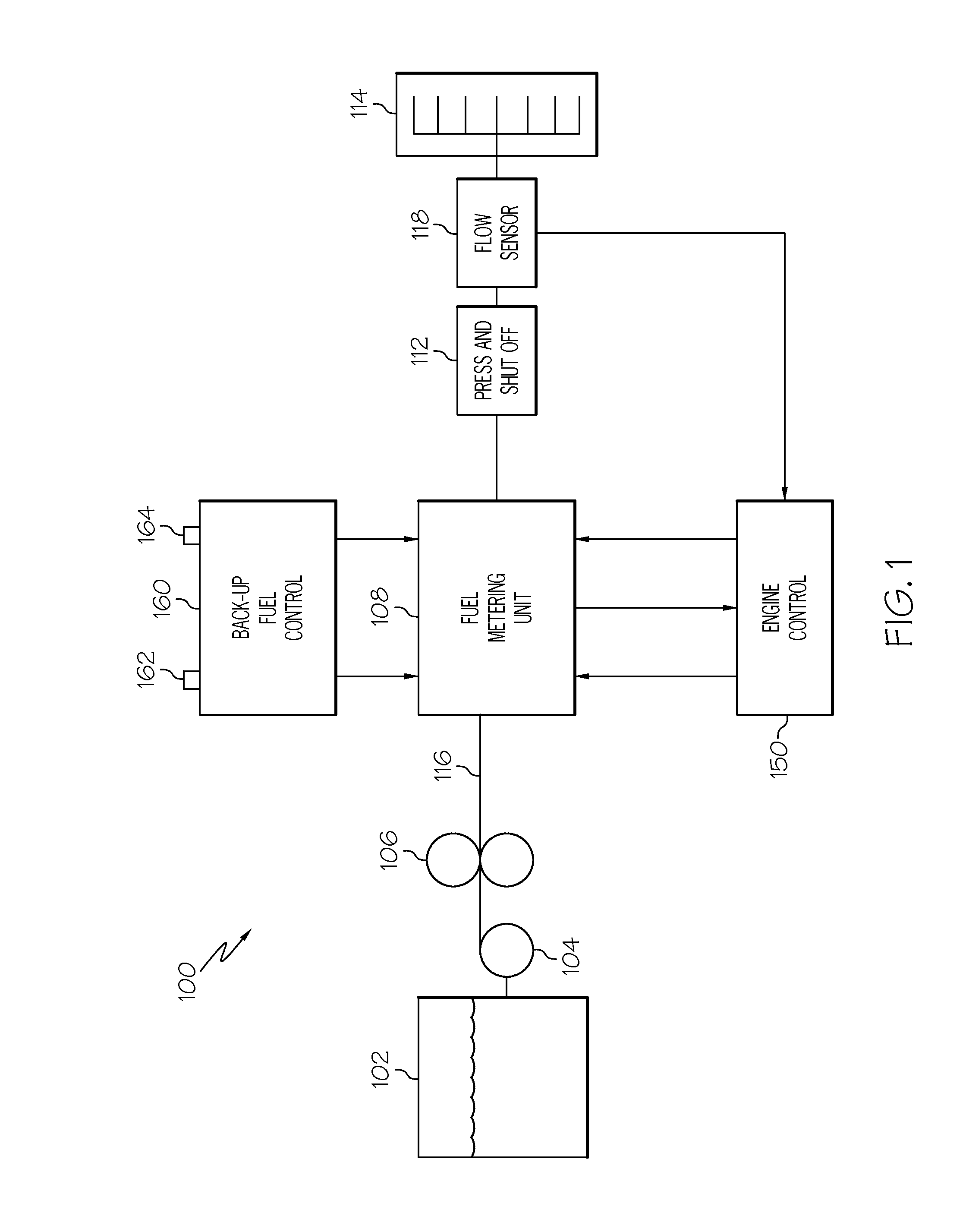
[0015]A simplified schematic diagram of one embodiment of a fuel delivery and control system for a gas turbine engine, such as a turbofan jet aircraft engine, is depicted in FIG. 1. The system 100 includes a fuel source 102, one or more pumps 104, 106, and a fuel metering unit 108. The fuel source 102, which is preferably implemented as a tank, stores fuel that is to be supplied to a gas turbine engine combustor 114. A supply line 116 is coupled to the fuel source 102 and, via the just-mentioned pumps 104, 106 and fuel metering unit 108, delivers the fuel to the combustor 114. It is noted that the supply line 116 is, for convenience, depicte...
PUM
 Abstract
Description
Claims
Application Information