Constraint weighted regulation of DC/DC converters

a converter and weighted technology, applied in the direction of electric variable regulation, process and machine control, instruments, etc., can solve the problems of input port deviating from its desired value, and achieve the effects of improving response dynamics and overall recovered power, fast dynamic response to environmental transients, and fast response times

Active Publication Date: 2015-09-22
BLUED ACQUISITION CORP
View PDF41 Cites 6 Cited by
  • Summary
  • Abstract
  • Description
  • Claims
  • Application Information

AI Technical Summary

Benefits of technology

[0010]In one set of embodiments, a control system or controller may be designed to improve the response dynamics and overall recovered power from a string plus branch or fully parallel-coupled solar array configuration. Each solar panel in the solar array may be coupled to a respective controller, which may sense an output voltage and output current produced by the solar panel, and control operation of a power converter (e.g. a DC / DC switching power converter) to output modified voltage and current corresponding to the solar panel into the series string, or into the parallel-connected configuration (an example of which is also provided in U.S. patent application Ser. No. 12 / 314,050, fully incorporated herein by reference). In one set of embodiments, the controller may include a hardware controller driven by analog or (digital) firmware control systems to regulate the input voltage of each power converter unit under indirect guidance of a Maximum Power Point Tracking (MPPT) controller to optimize and regulate the resultant power and achieve very fast dynamic response to environmental transients. In one set of embodiments, voltage management may be achieved by way of an inner control loop and a corresponding MPPT control system configured as an outer guidance loop. Consequently, solar panel arrays may achieve faster response times to transient events on the power bus that may affect the output and input of the power regulators, thus achieving higher power transfer and recovery levels than traditional MPPT-only based systems.
[0011]In most current systems, a control signal (e.g. PWM / Pulse Width Modulated / signal) of switching power converters that are coupled to the solar panels is controlled directly, i.e. parameters indicative of the input and output current and voltage associated with the power converter are used directly to control the duty cycle (value) of the PWM signal in a single loop. In contrast, various embodiments of a novel controller may include an inner loop that controls the duty cycle by monitoring a subset of the parameters (e.g. monitoring input voltage), and very rapidly maintaining desired current and voltage values / levels based on the subset of the parameters. A slower outer loop responsible for performing MPPT may control the reference point to which the inner loop may be regulating. The inner loop may monitor one or more of the inputs (e.g. input-port voltage, input-port current, output-port voltage, or output-port current, referring to ports of the power converter) to perform a regulation function associated with that input. While any one or more of these ports may be monitored, in many embodiments it is sufficient to monitor only one of these ports. For example the inner loop may monitor the input-port voltage, for performing an input voltage regulation function. The dual-loop configuration may thus successfully prevent transients at the output ports from being tracked to the input ports by implementing a sufficiently high bandwidth in the input-port regulating inner loop. To put it another way, the inner loop may rapidly respond to the transients on an output port to hold the input port at a desired (substantially fixed) point, whereas in the single loop configuration (with a slow response) the input port typically tracks the output port during transients, resulting in the input port deviating from its desired value, requiring time to potentially regulate the input port back to its desired state. To put it yet another way, by rapidly adapting the corresponding control signal (in this case a PWM signal) to adjust the input port to return to a desired operating point, the input port becomes desensitized to output modulations.
[0012]For example the output port of the power converter coupled to the solar panel may be affected by the DC / AC inverter coupled to the DC bus to which the power converters associated with the solar panels are also coupled. The DC / AC inverter may include a single-stage inverter @60 Hz, and may impress a 120 Hz power waveform onto the DC bus. This 120 Hz power waveform may then get superimposed onto the solar panel. However, by providing an inner control loop having a bandwidth that is faster than 120 Hz, the 120 Hz waveform may be prevented from causing the input port to track the output port during a transient event on the bus at the output of the power regulator. Therefore, the steady-state of the input port may be maintained through faster dynamics, that is, through a response time that is faster than the period corresponding to the frequency of the transient signal. In some embodiments, the inner control loop may operate on the order of 100-200 Hz, or even potentially as high as 1 KHz or more, and the outer control loop may operate on the order of 10-20 Hz with high precision, maintaining the desired MPPT accuracy.
[0013]In one set of embodiments, the converter unit coupled to the solar / photovoltaic panel may include a DC / DC converter also capable of adapting to output condition constraints. The DC / DC converter may be driven by analog or digital control systems (e.g. custom circuitry, or firmware driven microcontroller / processor based design, or a combination of both) to manage the output voltage of each unit to optimize and regulate the resultant bus voltage to a point which reduces overall system losses, maintains a low loss condition, and removes series-string non-idealities when the panels are series-connected. In one set of embodiments, instead of single-port regulation (e.g. regulating for the output port only or regulating for the input port only), a combination of input voltage and output voltage management and regulation may be performed within the converter. The source voltage and current characteristic may be shaped to correspond to an optimized power curve at the desired bus voltage (i.e. DC-bus voltage), to allow MPPT tracking according to the DC voltage bus. The optimized power curve may be tracked to hold the DC-bus voltage at the desired operating point.

Problems solved by technology

To put it another way, the inner loop may rapidly respond to the transients on an output port to hold the input port at a desired (substantially fixed) point, whereas in the single loop configuration (with a slow response) the input port typically tracks the output port during transients, resulting in the input port deviating from its desired value, requiring time to potentially regulate the input port back to its desired state.

Method used


Image

  • Constraint weighted regulation of DC/DC converters
  • Constraint weighted regulation of DC/DC converters
  • Constraint weighted regulation of DC/DC converters

Examples


Embodiment Construction

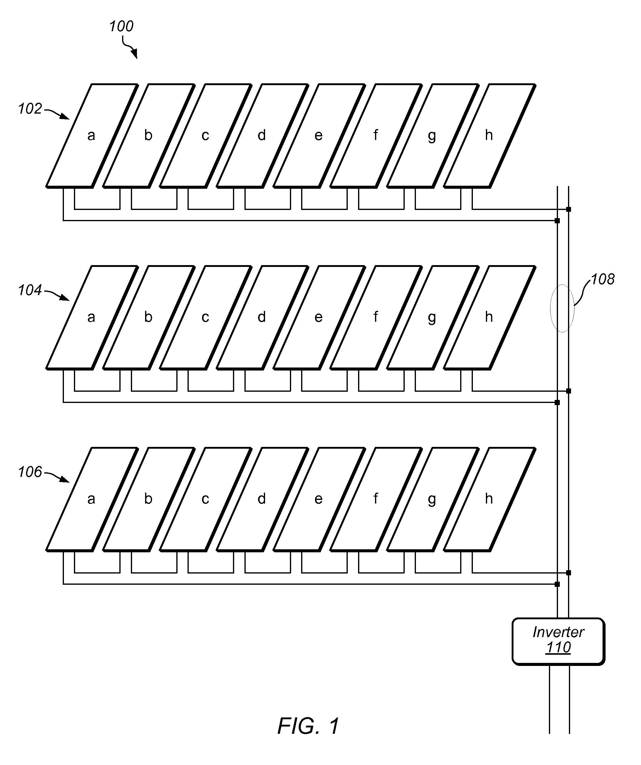
[0036]In solar array systems, many non-idealities may be mitigated by utilizing distributed Maximum Power Point Tracking (MPPT). Distributed MPPT usually includes insertion of a DC / DC converter or a similar power converter behind solar panels in the array, most commonly behind each and every solar panel in the array, to adapt the coupled solar panel's power transfer onto a high-voltage bus (typically a high-voltage DC bus) which connects the panels together via the DC / DC converters. A typical solar array 100 is shown in FIG. 1. Solar panel series-strings 102, 104, and 106 are coupled in parallel to bus 108, which may be a DC / DC bus. Each solar panel series-string includes solar panels a-h coupled in series to a respective bus, each of those respective buses coupling to bus 108 as shown to obtain parallel-coupled solar panel series-strings. An inverter 110 is coupled to bus 108 to ultimately drive a connected load, which may be coupled to the output of inverter 110.

[0037]An example o...


PUM


Abstract

A converter unit to improve overall recovered power in a photovoltaic array configuration. Each photovoltaic panel in the photovoltaic array may be coupled to a respective converter unit, which may include a controller to sense an output voltage and output current produced by the solar panel, and manage the output voltage of a corresponding power converter to optimize and regulate the resultant bus voltage to a point which reduces overall system losses, maintains a low loss condition, and removes series-string non-idealities when the panels are series connected. The controller may also adapt to output condition constraints. Instead of single-port regulation, a combination of input voltage and output voltage management and regulation may be performed within the converter. The source voltage and current characteristic may be shaped to correspond to an optimized power curve at the desired bus voltage to allow MPPT tracking according to the DC voltage bus. The optimized power curve may be tracked to hold the DC-bus voltage at the desired operating point.

Description

PRIORITY CLAIM AND INCORPORATION BY REFERENCE[0001]This application claims benefit of priority of U.S. Provisional Application Ser. No. 61 / 301,197 titled “System and Method for Constraint Weighted Regulation of a DC / DC Converter for Solar Array Applications”, filed Feb. 3, 2010, and whose inventors are Bertrand J. Williams and Sam B. Sandbote, and which is hereby incorporated by reference in its entirety as though fully and completely set forth herein.[0002]This application also incorporates by reference U.S. patent application Ser. No. 12 / 314,050 titled “Solar Power Array with Maximized Panel Power Extraction”, filed Dec. 3, 2008, and whose inventors are Bertrand J. Williams and Brett A. Raymis, and which is hereby incorporated by reference in its entirety as though fully and completely set forth herein.BACKGROUND OF THE INVENTION[0003]1. Field of the Invention[0004]This invention relates generally to the field of voltage regulation, and more particularly to the constraint weighted...

Claims


Application Information

Patent Timeline
Patent Type & Authority Patents(United States)
IPC IPC(8): H02J1/00H02J1/12H02M3/02
CPCH02J1/12H02M3/02Y10T307/653Y02E10/56H02J2300/26G05F1/67H02J3/381
Inventor WILLIAMS, BERTRAND J.SANDBOTE, SAM B.
Owner BLUED ACQUISITION CORP
Why Eureka
Try Eureka