Method of controlling a battery, computer readable recording medium, electric power generation system and device controlling a battery

a battery and computer readable technology, applied in the direction of greenhouse gas reduction, transportation and packaging, ac network load balancing, etc., can solve the problems of affecting the degree of stability of the frequency of the power grid to which the power generator is connected, affecting the output of power generators utilizing natural energy, and affecting the degree of stability of the power grid. , to achieve the effect of suppressing the effects of the power grid and prolonging the battery li

Inactive Publication Date: 2015-09-29
PANASONIC INTELLECTUAL PROPERTY MANAGEMENT CO LTD
View PDF7 Cites 4 Cited by
  • Summary
  • Abstract
  • Description
  • Claims
  • Application Information

AI Technical Summary

Benefits of technology

[0015]By means of the present invention, the setting of a target output value is enabled such that the trend of the target output value approximates the trend of the actual generated power output, based on not only the generated power output of the power generator, but also the slope to increase or decrease of the generated power. By this means, because the overall slippage between the target output value and the actually generated power output is reduced in order to smooth the fluctuations in the generated power output, and when the charge and discharge of the battery is performed in respect of only the difference between the target output value and the actual generated power output, the reduction in the amount of charge and discharge of the battery and the depth of the charge and discharge is enabled. As a result, a contrivance at lengthening the lifetime of the battery is enabled, while suppression the effects on the power grid caused by the fluctuations in the generated power from the power generator.

Problems solved by technology

However, the output of power generators utilizing natural energy may vary abruptly in correspondence with the weather and such like.
This abrupt fluctuation in the power output of this type of power generators applies a gross adverse impact on the degree of stability of the frequency of the power grid they are connected to.
This adverse impact becomes more pronounced as the number of consumers with power generators using natural energy increases.

Method used


Image

  • Method of controlling a battery, computer readable recording medium, electric power generation system and device controlling a battery
  • Method of controlling a battery, computer readable recording medium, electric power generation system and device controlling a battery
  • Method of controlling a battery, computer readable recording medium, electric power generation system and device controlling a battery

Examples


embodiment 1

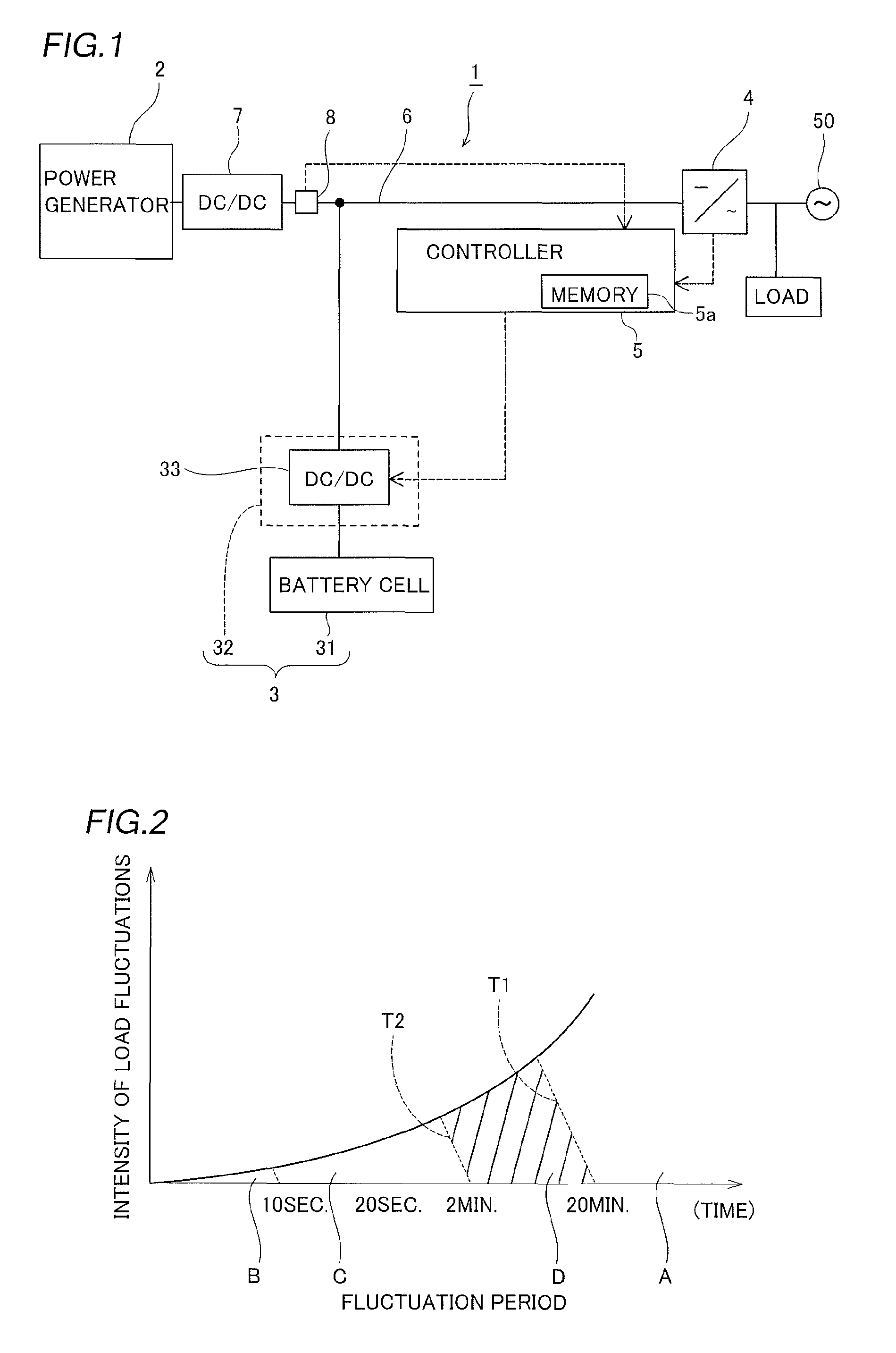
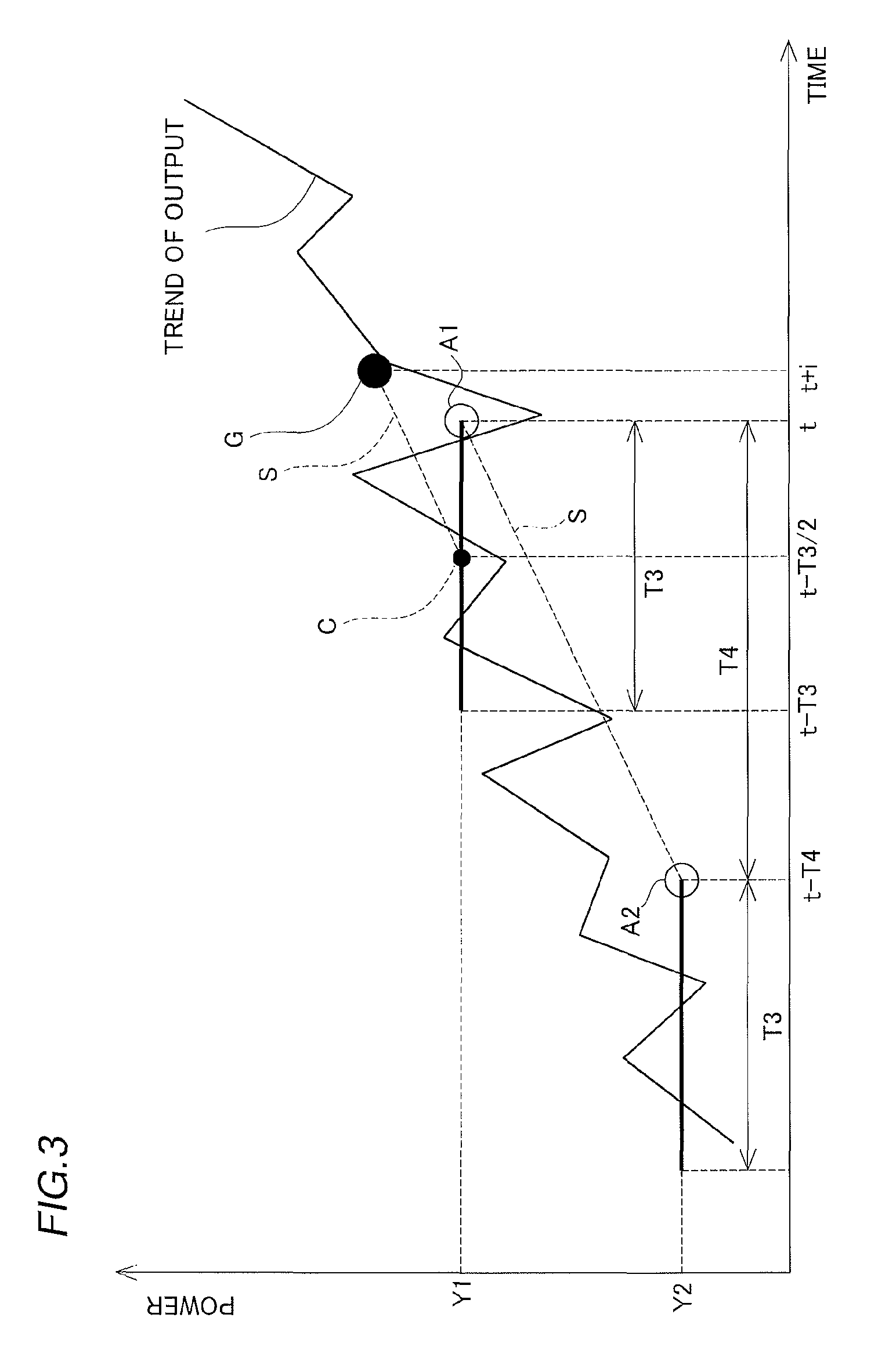
[0035]Firstly, the configuration of the power generation system of the first embodiment of the invention is explained while referring to FIG. 1˜3.

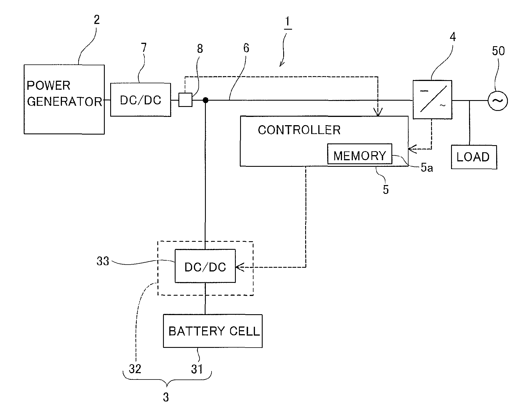
[0036]As shown in FIG. 1, the power generation system 1 has the power generator 2 comprised of a solar cell electrical generator employing sunlight, connected to the power grid 50. The power generation system 1 provides an battery 3 enabling electrical storage of the power generated by means of the power generator 2, and a power output unit 4 including an inverter which outputs electrical power stored by battery 3 as well as power generated by means of the power generator 2 to the power grid 50, and a controller 5 controlling the charging and discharging of the battery 3. Now, the power generator 2 is preferably a generator utilizing renewable energy and, for example, may employ a wind power generator and the like.

[0037]The DC-DC converter 7 is connected in series on the bus 6 connecting the power generator 2 and the power output unit 4. T...

embodiment 2

[0064]Next, an explanation is provided concerning the power generation system 100 of the second embodiment of the present invention. In this embodiment, unlike in embodiment 1, an example where the sampling periods are made longer when the fluctuations in the generated power are great is explained.

[0065]The power generation system 100 provides a controller 101 instead of the controller 5 of embodiment 1. The configuration, other than the controller 101, is the same as the power generation system 1 of embodiment 1.

[0066]When the fluctuations in the generated power are within a specific range, the controller 101 computes the target output value by setting the sampling period at 20 minutes, and in order to compute the slope of the moving average values, the time interval between the moving average values is set at 20 minutes. Moreover, when the fluctuations in the generated power output are outside a specific range, the controller 101 computes the target output value by not only extend...

embodiment 3

[0074]Next, an explanation is provided concerning the power generation system 200 of the third embodiment of the present invention, while referring to FIG. 7 and FIG. 8. In this embodiment, unlike in embodiment 1, an example where the sampling periods are made longer when the fluctuations in the generated power are great is explained.

[0075]As shown in FIG. 7, the power generation system 200 provides a controller 201 instead of the controller 5 of embodiment 1. The configuration, other than the controller 201, is the same as the power generation system 1 of embodiment 1.

[0076]When the fluctuations in the generated power are within a specific range, the controller 201 computes the target output value by setting the sampling period at 20 minutes, and in order to compute the slope of the moving average values, the time interval between the moving average values is set at 20 minutes. Moreover, when the fluctuations in the generated power output are outside a specific range, the controlle...


PUM


Abstract

The method of controlling a battery storing electric power generated by a power generator generating electric power using renewable energy comprises detecting an amount of electric power generated by the power generator at a first time and a second time that is prior to the first time; computing a rate of increase or decrease of the amount of electric power between the first time and the second time; computing a target output value for the electric power to be supplied to an electric power transmission system based on the rate, and supplying to the electric power transmission system electric power corresponding to the target output value from at least one of the power generator and the battery.

Description

CROSS REFERENCE TO RELATED APPLICATIONS[0001]This application is a continuation of International Application No. PCT / JP2011 / 051563, filed Jan. 27, 2011, which claims priority from Japanese Patent Application No. 2010-015236, filed Jan. 27, 2010, the entire contents of which are incorporated herein by reference.FIELD OF INDUSTRIAL USE[0002]The present invention relates to a method of controlling a battery, a computer readable recording medium, an electric power generation system and a device controlling a battery.PRIOR ART[0003]In recent years, the number of instances where power generators (solar cells etc.) utilizing natural energy such as wind power or sunlight are connected to consumer homes in receipt of a supply of alternating power from an electricity substation has increased. These types of power generators are connected to the power grid subordinated to the substation, and power generated by the power generators is output to the power consuming devices side of the consumer l...

Claims


Application Information

Patent Timeline
Patent Type & Authority Patents(United States)
IPC IPC(8): H02J1/00H02J7/00H02J3/38H02J7/34H02J3/32H02J7/35
CPCH02J3/383H02J1/00H02J3/32H02J7/00H02J7/34H02J7/35Y02E10/563Y02E10/566Y02E70/30Y10T307/50Y02P90/50H02J2300/24H02J3/381Y02E10/56
Inventor YAMADA, YOHEIIKEBE, HAYATOSAKAI, SOUICHI
Owner PANASONIC INTELLECTUAL PROPERTY MANAGEMENT CO LTD
Why Eureka
Try Eureka