Method for producing a large steel tube

a technology of steel tubes and steel tubes, which is applied in the direction of pipes, rigid pipes, pipes/joints/fittings, etc., can solve the problems of unfavorable stress states, inability to achieve uniform upsetting strength of the material over the circumference of the tube, and inability to achieve large steel tubes. achieve the effect of shortest possible production time, improved mechanical-technological properties, and precise possible concentric straightening

Active Publication Date: 2015-10-13
EISENBAU KRAMER
View PDF8 Cites 1 Cited by
  • Summary
  • Abstract
  • Description
  • Claims
  • Application Information

AI Technical Summary

Benefits of technology

[0011]One object of this invention is to provide a method for producing large steel tubes with which the manufacture of high-quality tubes is achieved with the most precise possible concentric straightening and the shortest possible production time, and to furnish correspondingly embodied tubes, in which the mechanical-technological properties of the material are also to be improved.
[0013]With the provisions in the combination recited, not only can the target diameter be established properly, but in the process of the concentric straightening, a stress-relieving treatment is also done. In this way, not only is the tube tolerance, especially the ovality, improved in a short time by uniform plastic deformation of the material, but the intrinsic stress performance of the tubular body is improved as well. Not only are the stresses generated by forming the sheet-metal material mechanically in the fundamental material reduced, but the thermally created stresses caused by the longitudinal seam welding of the sheet-metal material formed to make the tube are diminished as well. Overall, the mechanical-technological properties of the tube are improved by the method, such as the upsetting strength and the collapsing resistance, for example. As calculations in the context of research and development work have proven, the intrinsic stress performance after impansion, depending on the degree of impansion, is reduced to a minimum, and diminishing stress practically completely is made possible, without requiring a complicated heat treatment, such as a low-stress annealing, for instance at approximately 600° C., and advantages arising from the heat treatment can be avoided. Because of the uniform upsetting over the outer surface of the tube, the intrinsic stresses generated by the production process diminish in the longitudinal and circumferential directions in the basic material and in the welded seam. As experiments by the applicants have shown, one reason for the improvements is evidently that the residual stress state is reversed. After the impansion, there is tensile stress on the inside of the tube and compressive stress on the outside of the tube. With raw materials plated on the inside, the impansion from outside provides additional advantages, since the vulnerable inside surface is not damaged or strained. As a result, there is no lessening of the corrosion properties of the internal material. In coating materials, for instance from alloy 625, the corrosion resistance is even improved from internal residual stresses.

Problems solved by technology

Straightening large steel tubes, in particular, by such methods or provisions is complicated, and problems and solutions for concentric straightening are not found in this reference.
Although a target diameter can be established through a relatively great effort in this way, with the straightening, a uniform upsetting strength of the material over the circumference of the tube, in particular, fails to be achieved.
In this operation, however, unfavorable stress states can be created in the tubular body, and as a result the upsetting strength and hence the resistance to collapsing of the pipeline may lessen.
In coated tubes, so-called clad tubes, damage to the material can also occur, so that such tubes can often not be calibrated by this method.

Method used


Image

  • Method for producing a large steel tube
  • Method for producing a large steel tube
  • Method for producing a large steel tube

Examples


Embodiment Construction

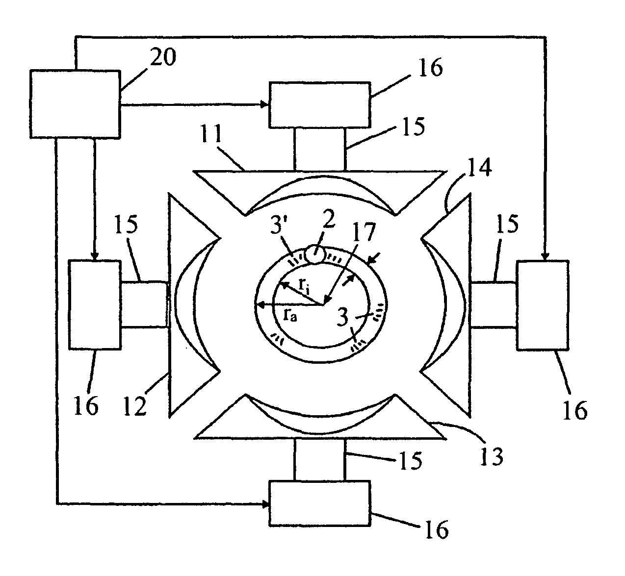
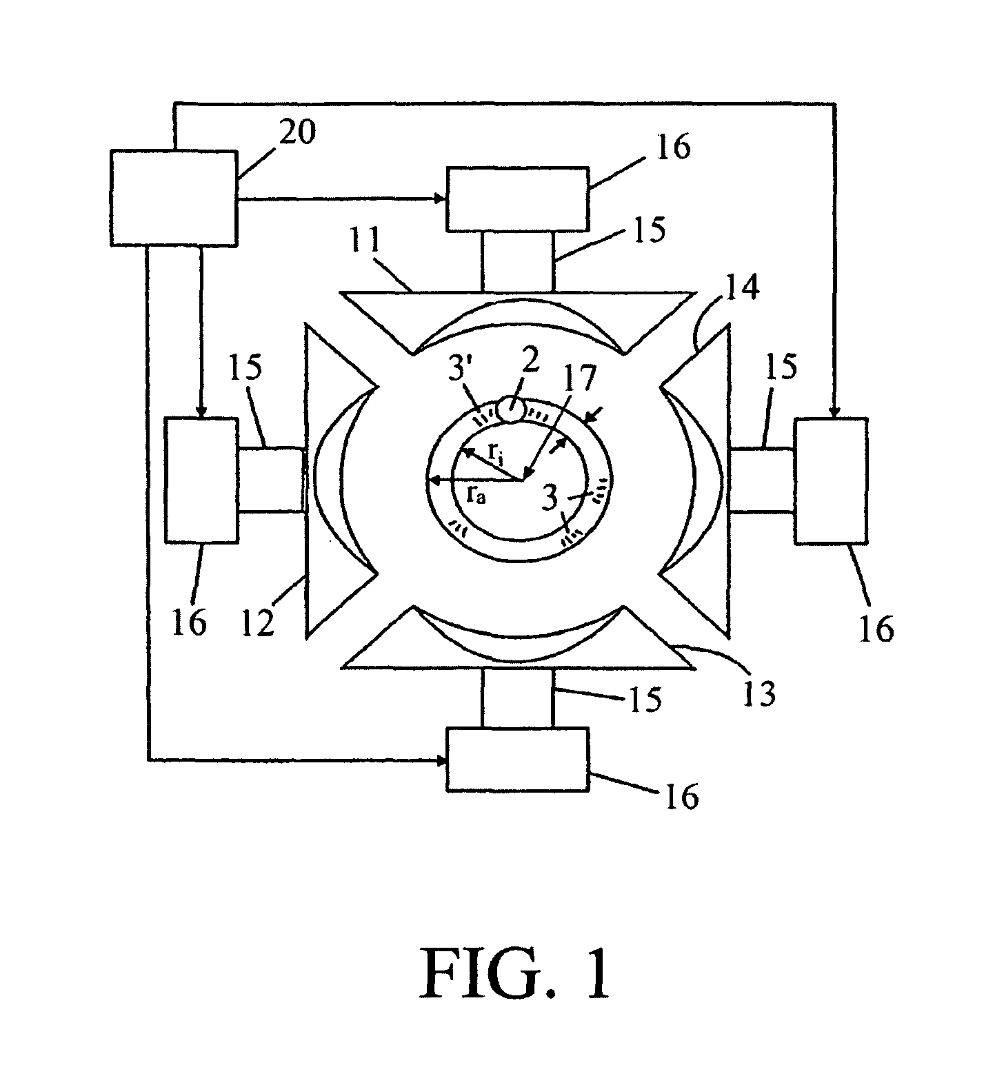
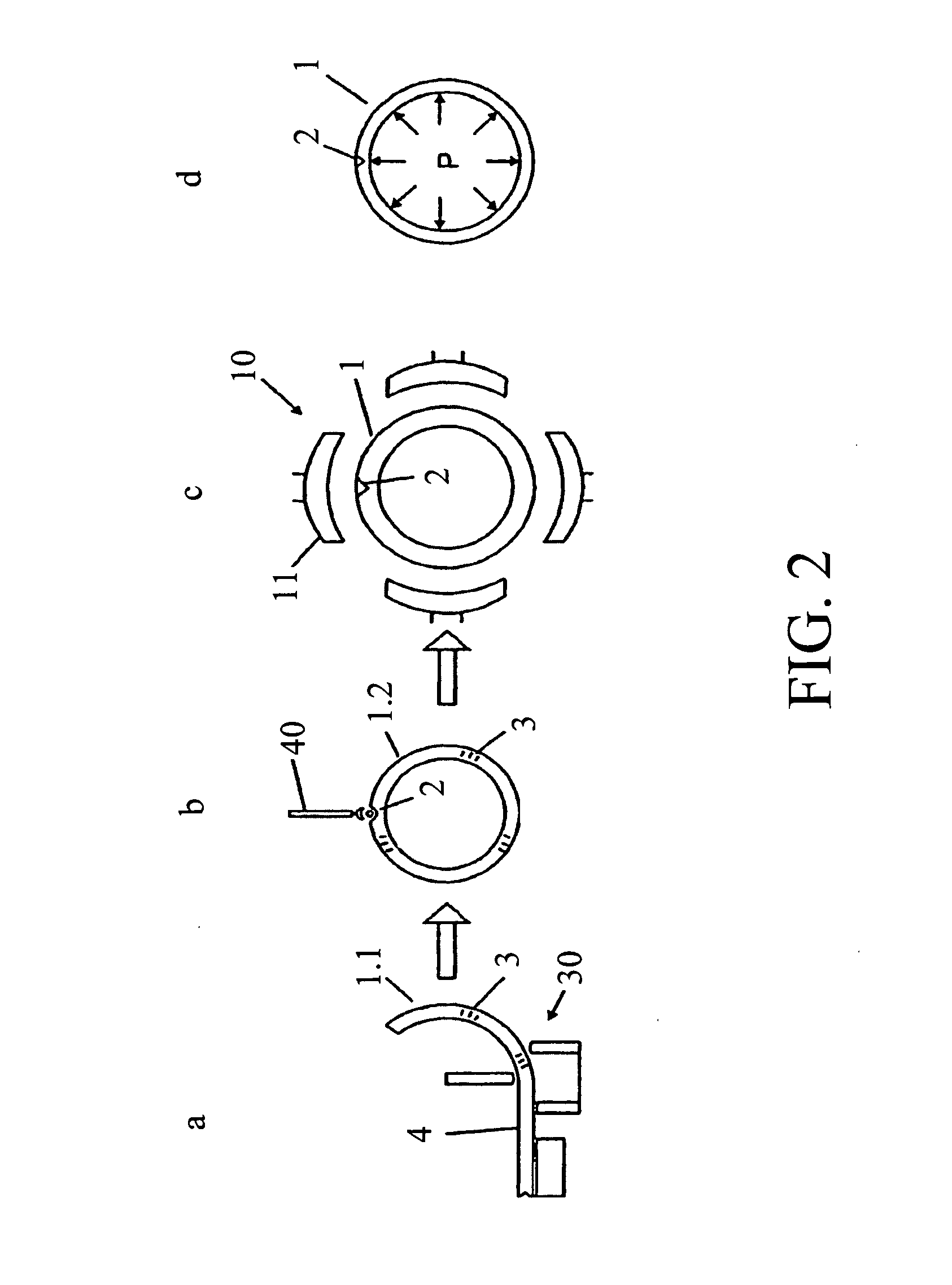
[0022]FIG. 1 in an axial plan view shows a tube 1 of round cross section, with an inner radius ri and an outer radius ra, the difference between which defines a wall thickness t. The tube 1 has a longitudinally extending welded seam 2. In the tube wall, mechanical and thermal stress regions 3, 3′ are present, as a consequence of the mechanical forming process and as a consequence of the influence of heat in the welding.

[0023]The straightening machine or straightening device 10 has a plurality of welding devices, distributed uniformly in the circumferential direction and disposed at an identical location in the axial direction, each with respective straightening shells 11, 12, 13, 14, which are mounted replaceably each on their own holder 15 and are provided, on their side toward the tube 1, with a surface form adapted to the surface contour of the tube 1, which surface form extends in the circumferential direction along the tube surface, so that when all the straightening shells are...


PUM

PropertyMeasurementUnit
wall thicknessesaaaaaaaaaa
plastic deformationaaaaaaaaaa
hydraulic stressaaaaaaaaaa

Abstract

A method for producing a steel tube, wherein a steel sheet is formed into tubular body having a round cross section in a bending process, welded in a subsequent welding process along longitudinal edges facing each other for producing a continuous longitudinal seam, and then subjected to a stress-relieving treatment. The production quality is improved, with reduced production time, because the stress-relieving treatment is performed in a process for concentrically truing along the circumference in at least one segment relative to the longitudinal axis thereof, while cold forming by compression (FIG. 1). The mechanical technological properties of the material are also thereby improved.

Description

BACKGROUND OF THE INVENTION[0001]1. Field of the Invention[0002]This invention relates to a method for producing a steel tube, in which a metal sheet or coil is formed in a bending process to a tubular body having a round cross section, is welded in an ensuing welding process along the longitudinal edges facing one another to produce one continuous seam, and is then subjected to a stress-relieving treatment.[0003]2. Discussion of Related Art[0004]One method of this type is described in German Patent Disclosure DE 10 2006 010 040 B3. In this known method, the tube is compressed by a straightening machine from the outer circumference, by a plurality of welding devices, offset in a circumferential direction and located at an identical location in the axial direction, for concentric straightening. The welding devices have straightening shells adapted to the shape of the outer cross section of the tube. The straightening shells can be driven, for instance hydraulically, individually or i...

Claims


Application Information

Patent Timeline
Patent Type & Authority Patents(United States)
IPC IPC(8): B21D3/10B21C37/30B21C37/08B21D5/14B21D5/10
CPCB21D3/10B21C37/0807B21D5/14B21D5/10B21C37/30
Inventor BEISSEL, JOCHEMREICHEL, THILO
Owner EISENBAU KRAMER
Why Eureka
Try Eureka