
Method for producing a large steel tube
a technology of steel tubes and steel tubes, which is applied in the direction of pipes, rigid pipes, pipes/joints/fittings, etc., can solve the problems of unfavorable stress states, inability to achieve uniform upsetting strength of the material over the circumference of the tube, and inability to achieve large steel tubes. achieve the effect of shortest possible production time, improved mechanical-technological properties, and precise possible concentric straightening
- Summary
- Abstract
- Description
- Claims
- Application Information
AI Technical Summary
Benefits of technology
Problems solved by technology
Method used
Image

Examples
Embodiment Construction
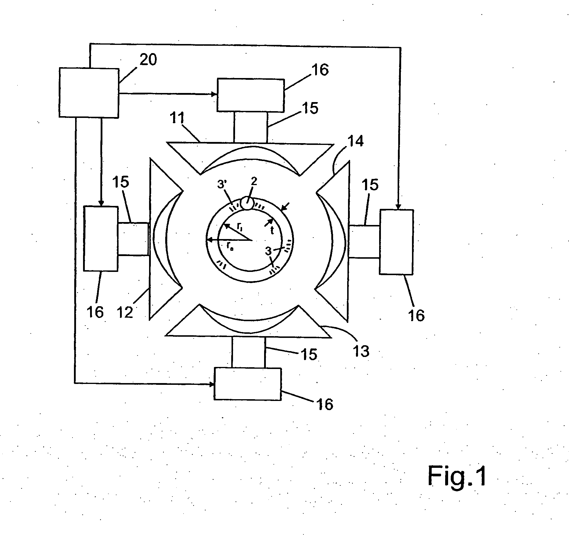
[0022]FIG. 1 in an axial plan view shows a tube 1 of round cross section, with an inner radius ri and an outer radius ra, the difference between which defines a wall thickness t. The tube 1 has a longitudinally extending welded seam 2. In the tube wall, mechanical and thermal stress regions 3, 3′ are present, as a consequence of the mechanical forming process and as a consequence of the influence of heat in the welding.
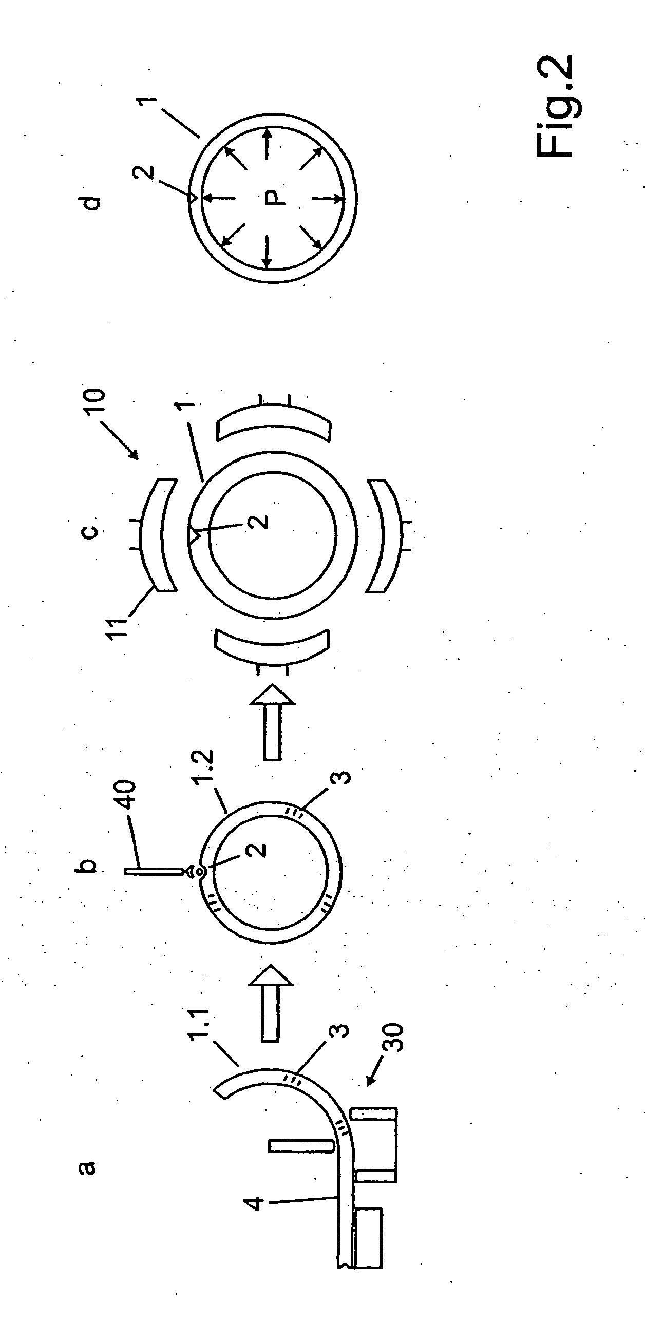
[0023]The straightening machine or straightening device 10 has a plurality of welding devices, distributed uniformly in the circumferential direction and disposed at an identical location in the axial direction, each with respective straightening shells 11, 12, 13, 14, which are mounted replaceably each on their own holder 15 and are provided, on their side toward the tube 1, with a surface form adapted to the surface contour of the tube 1, which surface form extends in the circumferential direction along the tube surface, so that when all the straightening shells are...
PUM
| Property | Measurement | Unit |
|---|---|---|
| Diameter | aaaaa | aaaaa |
| Mechanical properties | aaaaa | aaaaa |
| Circumference | aaaaa | aaaaa |
Abstract
Description
Claims
Application Information