
Drug eluting balloon for the treatment of stenosis and method of manufacturing the balloon

a technology of stenosis and balloon, which is applied in the direction of balloon catheters, dilators, medical devices, etc., can solve the problems of severe consequences for patients, obstruction of blood vessels, and known methods, but not without defects, so as to prevent the rinsing effect, restrain the dispersion of drugs, and prevent the effect of rinsing

Active Publication Date: 2015-10-27
INVATEC TECH CENT
View PDF3 Cites 3 Cited by
  • Summary
  • Abstract
  • Description
  • Claims
  • Application Information

AI Technical Summary

Benefits of technology

The solution effectively retains a substantial amount of drug under the folds, preventing loss and dispersion, ensuring higher drug delivery to the target site and minimizing secondary effects by maintaining drug containment until the balloon reaches the intervention site.

Problems solved by technology

However, this mechanical action may cause in some patients, at the site of intervention, a cell hyperproliferation known as restenosis, which may again lead to an obstruction of the blood vessel and to severe consequences to the patient.
This known method, however, is not without defects.
This at least partial removal of drug from the balloon determines some undesirable consequences.
Firstly, the administration of the drug to the stenosis area is lower than expected and a priori unknown.
Secondly, an amount of the drug is dispersed in unintended districts of the body, with consequent undesirable secondary effects due to the intrinsic toxicity of the antiproliferative drug that is used.
Moreover, it has been observed that after the drug has been carried close to the stenosis, it can immediately be lost after the normal blood flow has been restored.
It has been observed however that, when immersed into a blood environment, this type of balloon may partially lose an amount of drug before reaching the final destination, as the folds tend to open or the plasma tends to reach the cavity under the folds by capillarity.

Method used


Image

  • Drug eluting balloon for the treatment of stenosis and method of manufacturing the balloon
  • Drug eluting balloon for the treatment of stenosis and method of manufacturing the balloon
  • Drug eluting balloon for the treatment of stenosis and method of manufacturing the balloon

Examples


Embodiment Construction

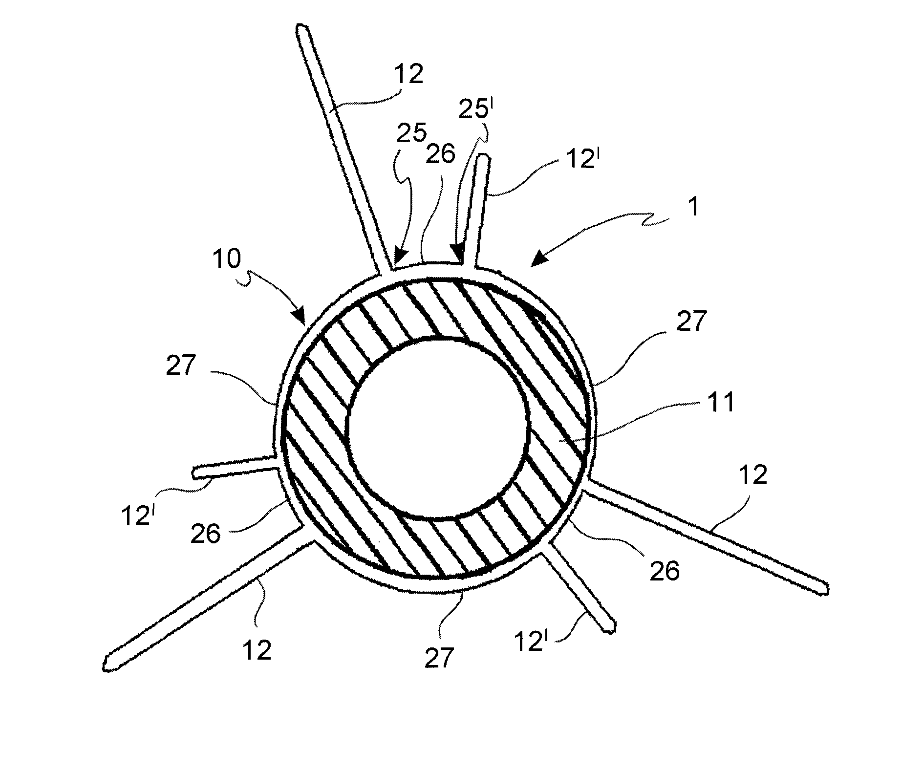
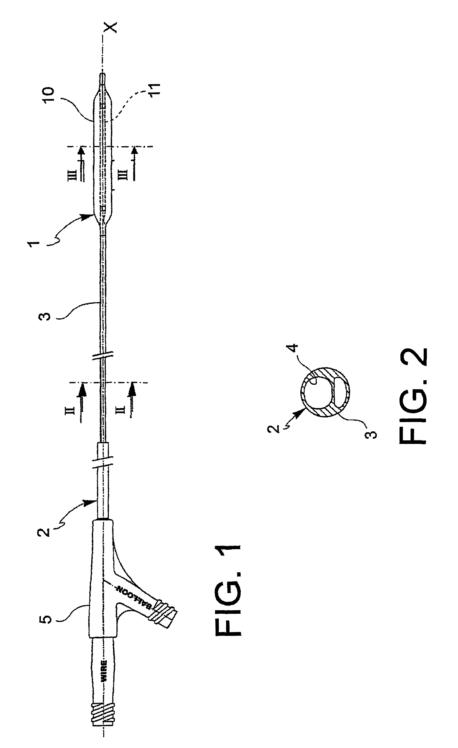
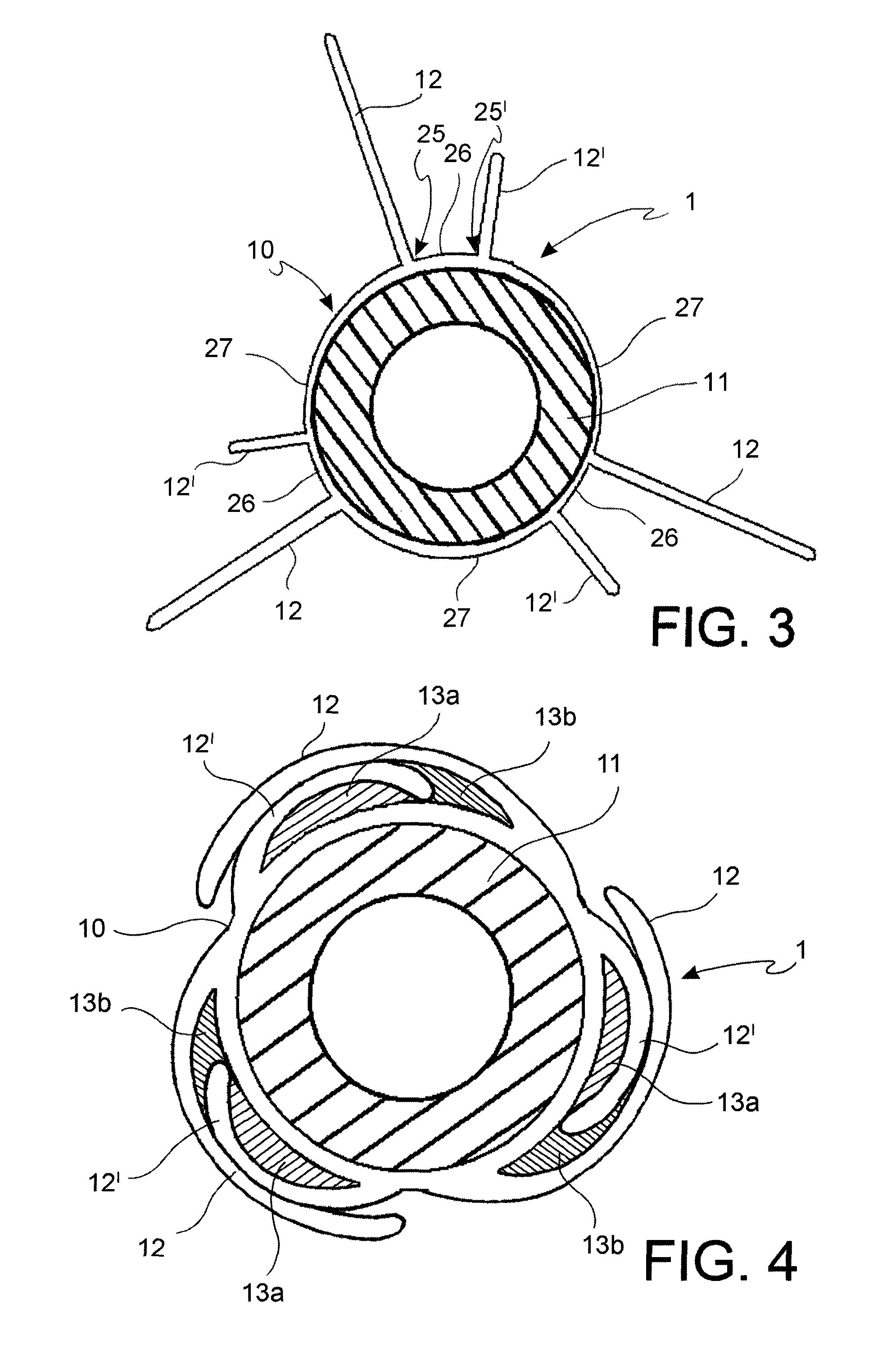
[0063]With reference to the figures, an angioplasty balloon, indicated with the numeral 1, is mounted at the distal end of a catheter 2.

[0064]The catheter 2 further comprises an elongated tubular body 3 that is provided with a plurality of lumens 4, 4′ (passages for the guide-wire and for inflating or deflating the balloon, respectively), and a connector means 5 at the proximal end thereof. In the figure, the lumens 4, 4′ are positioned side by side, but a coaxial arrangement may also be foreseen.

[0065]The balloon 1 is suitable to alternatively adopt a deployed configuration and a collapsed configuration. The balloon is brought to the deployed configuration by means of the injection of a pressurized inflating fluid, and vice versa it is brought to the collapsed configuration by means of the suction of the same inflating fluid.

[0066]The angioplasty balloon of the invention can be manufactured in any polymeric material that is conventionally used for these applications, such as, witho...


PUM

PropertyMeasurementUnit
αaaaaaaaaaa
αaaaaaaaaaa
circumferential lengthaaaaaaaaaa

Abstract

A drug eluting angioplasty balloon (1, 101) suitable to adopt a deployed configuration and a collapsed configuration, the balloon having an outer wall (10) disposed around a core (11) defining an axis (X). The balloon (1, 101) comprising in the collapsed configuration a plurality of folds (12, 12′, 112) that are laid in a tangential direction about the core (11) and form a plurality of cavities (13a, 13b, 113) loaded with a drug (14), the cavities (13a, 13b, 113) are comprised between the folds (12, 12′, 112), wherein the folds (12, 12′, 112) originates from distinct longitudinal lines (25, 25′, 125, 125′) along the outer wall (10), are arranged in pairs and are circumferentially wrapped about the core (11) in such a way that a fold of one pair overlaps an adjacent fold of another pair and are wrapped in opposite directions.

Description

FIELD OF THE INVENTION[0001]The present invention relates to a balloon catheter for angioplasty and pharmacologic treatment of stenosis. The invention further relates to a method for manufacturing the said balloon catheter.BACKGROUND ART[0002]Balloon catheters for the angioplasty treatment of stenosis within the human body circulatory system have been known for a long time. These catheters comprise a balloon at the distal end thereof. The balloon catheter is inserted within the blood vessels with the balloon in a deflated configuration and is brought proximate to the site of stenosis. At this point, the balloon is inflated for a relatively short time span to obtain the dilation of the vessel and concomitantly a mechanical treatment of the stenosis, which is suitable to restore the section of the blood vessel. However, this mechanical action may cause in some patients, at the site of intervention, a cell hyperproliferation known as restenosis, which may again lead to an obstruction o...

Claims


Application Information

Patent Timeline
Patent Type & Authority Patents(United States)
IPC IPC(8): A61M31/00A61M37/00A61M25/10A61L29/16
CPCA61M25/104A61L29/16A61M25/1038A61L2300/416A61L2300/62A61L2300/63A61M25/1011A61M2025/1004A61M2025/105A61M2025/1031A61M2025/1052
Inventor MORERO, MASSIMOSCALVINI, GIOVANNI
Owner INVATEC TECH CENT
Learn More